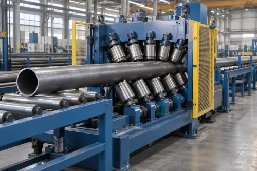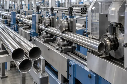
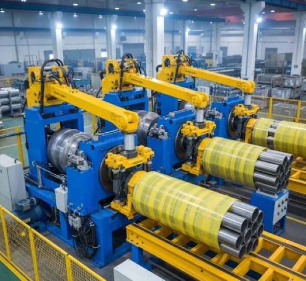
A hollow tube becomes a precision product by passing through a converging die under controlled pulling force, often with a plug or mandrel supporting its inside diameter. By the end, you will be able to map the complete production sequence, distinguish drawing from tube-mill and cold-pilger routes, and judge whether a draw bench matches your material, dimensions, tolerances and production volume.
Key takeaways
- Prepare, point and lubricate the shell before the first drawing pass.
- Choose a draw bench for controlled reduction and precise finished dimensions.
- Set pass limits from material, wall reduction, lubrication and work-hardening behaviour.
- Verify diameter, wall thickness, straightness and surface defects after drawing.
How tube drawing changes a tube from preparation to inspection
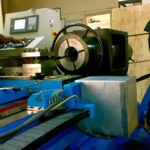
A tube changes from a cut, prepared shell into a controlled-dimension product through three stages: preparation, repeated pulling and post-draw verification. A Tube Draw Bench combines tube pointing, gripping, die holding, internal tooling, traction and lubrication; it is more than a sizing stand.
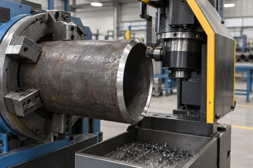
1. Before drawing, cut the incoming tube to length and inspect it for seams, laps, dents and excessive wall variation. Swage or point one end to reduce its diameter so the pointed section can pass through the die and be gripped by the carriage.
Clean away scale, oil and debris, then apply the specified drawing lubricant. Set the die, plug or mandrel concentrically and check tooling condition, alignment and lubricant viscosity.
2. During drawing, a Tube Drawing Machine pulls the tube through a converging die, reducing its outside diameter and, with internal support, controlling its inside diameter and wall thickness. Sinking uses no internal tool; fixed plugs, floating plugs and moving mandrels provide progressively greater control.
Draw speed and force must match the alloy, reduction and lubrication. Measure each pass, and anneal the tube between passes when work hardening limits further reduction.
3. After drawing, remove lubricant and oxide before inspecting the surface. Straighten and size the tube, then check outside diameter, inside diameter, wall thickness, length, ovality and straightness. Look for die lines, scratches, scoring, galling, chatter marks and eccentric walls; clean inspection prevents lubricant from hiding defects.
Reject or rework tubes with inherited seams or laps that compromise service.
Choosing between a draw bench, tube mill and cold pilger mill
The feedstock decides the starting point: a tube mill forms strip and welds it into tube, while a Tube Draw Bench and cold pilger mill process an existing hollow. Choose the route against reduction, length, wall control and finish—not machine name alone.
| Option | Feedstock and reduction | Best fit | Main limitation |
|---|---|---|---|
| Tube mill | Flat strip; forms and welds continuously, with sizing rolls after welding | Welded tube, high output, long continuous products and thin-wall production from strip | The weld zone remains a critical inspection point, and it is less flexible for large reductions or difficult alloys |
| Tube Draw Bench | Welded or seamless tube; pulls it through a die, with a plug or mandrel when wall control is needed | Tight outside diameter, controlled wall thickness, thin walls, long precision lengths, small batches and demanding surface finishes | Intermittent loading, pointing, gripping and unloading reduce throughput; multiple passes and annealing add time |
| Cold pilger mill | Seamless hollow; reciprocating rolls reduce diameter and wall thickness together | Large area reductions, thin-wall seamless tube, difficult alloys and high dimensional or surface requirements | Tooling and cycle control are complex, and the process is less suited to welded feedstock or continuous high-speed output |
Select a Tube Drawing Machine when dimensional flexibility and surface quality outweigh continuous throughput. Use a pilger mill when one route must remove substantial cross-section from seamless hollow before finishing passes. Choose a tube mill when welded, long-length production dominates; downstream drawing can then improve its dimensions and finish.
Large reductions still require several passes, lubrication control and interpass annealing to prevent cracking and work hardening.
Drawing methods, pass limits and material preparation
Sinking is the fastest, simplest route, but it gives you the least control: the die reduces the outside diameter without supporting the bore, so wall thickness and inside diameter can drift. Plug or mandrel drawing adds internal support and improves dimensional accuracy, although friction, setup time and alignment become more demanding.
| Method | Dimensions and finish | Speed and defect risk |
|---|---|---|
| Sinking | Lowest control of inside diameter and wall thickness; outside finish depends heavily on die condition | Fast setup; eccentricity, uneven wall and bore damage are harder to correct |
| Fixed-plug | Strong control of bore, wall reduction and surface finish | Reliable plug retention and lubrication are essential; excess friction can cause scoring or seizure |
| Floating-plug | Good accuracy and internal finish when plug position remains stable | Faster to change than a rigid mandrel; speed, friction and reduction balance can cause plug drift, laps or wall variation |
| Moving mandrel | Best control of wall thickness, bore and reduction; supports demanding finishes | Slower and more complex; misalignment or excessive force can mark the bore, buckle the tube or break the mandrel |
Do not choose pass reductions by percentage alone. Draw force, alloy ductility, die and plug angles, lubrication, target dimensions and work hardening set the practical limit. A large reduction in one pass can crack the tube, gall the tooling or leave residual stress; intermediate annealing restores ductility.
Prepare each pass by:
- Cleaning scale, oil and chips from the tube and tooling.
- Annealing when hardness or accumulated cold work blocks the next reduction.
- Pointing or swaging the end so the carriage can grip it.
- Checking concentric alignment, lubricant cleanliness and viscosity before the Tube Drawing Machine runs. Precision Engineering depends on these controls, not tooling accuracy alone.
Specifications that determine whether a Tube Draw Bench fits
Select a Tube Draw Bench from the tube data outward: record feed OD, wall thickness, length, material grade, weld or seamless route, yield strength and required finished dimensions. Include the smallest and largest sizes, not just the average order.
A bench that draws one automotive tube accurately can lack the force, stroke or tooling range for another.
Compare these items before requesting a quotation:
- Maximum draw force, carriage stroke, draw length, carriage speed and motor power against your pass schedule and production rate.
- Die-holder capacity, plug or mandrel arrangement, concentric alignment adjustment and tooling geometry for the required OD, ID and wall reduction.
- Pointing or swaging method, grip length and loading method; an inadequate pointed end slips in the carriage and stops the cycle.
- Lubricant application, filtration, viscosity control and cleanliness monitoring; contaminated lubricant scores the tube and accelerates die wear.
- Draw-speed control, pass-by-pass OD and wall measurement, alarm limits, recipe storage and inspection intervals for die and plug wear.
| Specification | Compare | Why it matters |
|---|---|---|
| Incoming tube | OD, wall, length, grade and weld condition | Confirms tooling, force and pass capacity |
| Machine rating | Force, stroke, speed and maximum tube length | Prevents overload or unused capacity |
| Tooling | Die angle, bearing length, plug type and alignment | Controls wall uniformity, finish and concentricity |
| Process control | Lubrication, speed, measurement and wear checks | Makes Precision Engineering repeatable |
When evaluating equipment from Gallium Equipment Pvt. Ltd., ask for the operating envelope and measured tolerances at each pass, not a generic capacity figure.
Related product
 | We are proficiently engaged in manufacturing of high quality Draw Bench. View product → |
Applications, standards and the finishing route after drawing
Cold-drawn tubes serve Automotive Tubes, hydraulic and pneumatic power systems, instrument lines, heat exchangers and precision mechanical assemblies. Select the standard by route and service; seamless and electric-welded products are not interchangeable.
| Specification | Route or application | What it controls |
|---|---|---|
| EN 10305-1 | Seamless cold-drawn tube | European precision dimensions and delivery condition |
| EN 10305-2 | Electric-welded cold-drawn tube | Welded precision tube requirements |
| EN 10305-3 | Electric-welded cold-sized tube | Sizing without the same drawing route |
| EN 10305-4 | Seamless cold-drawn tube | Hydraulic and pneumatic systems |
| EN 10305-5 | Welded cold-drawn square or rectangular tube | Formed sections |
| ASTM A513 | Electric-resistance-welded mechanical tubing | Route, inspection and mechanical properties |
| ASTM A519 | Seamless carbon or alloy mechanical tubing | Seamless route and mechanical properties |
A finishing route converts the drawn shell into a controlled, identifiable product:
- Straighten and size the tube; measure outside diameter, wall thickness, ovality and length.
- Cut to length, then face, chamfer and deburr only when the assembly requires a defined end.
- Wash and dry it before inspection, because lubricant and oxide can hide die lines, scoring, galling and chatter marks.
- Apply eddy-current or ultrasonic inspection, with hydrostatic testing when the purchase specification demands pressure verification.
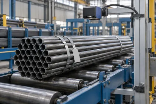
- Mark the grade, size, heat or batch reference, then bundle without denting the ends.
Specify tube finishing equipment as this process chain, not as a generic finishing line. Extra end work or testing adds handling, cost and damage risk when the drawing, end geometry and inspection class do not require it.
Frequently asked questions
How does a tube drawing machine change a prepared tube?
The machine points and grips the tube, pulls it through a die over or around internal tooling, then verifies diameter, wall thickness, straightness and surface quality.
When should you choose a tube draw bench instead of a tube mill or cold pilger mill?
Choose a draw bench for cold sizing, wall control and precision batches. Use a tube mill for continuous strip-to-tube production, and a cold pilger mill for substantial reduction and demanding seamless-tube work.
What determines the number of tube drawing passes?
Material grade, starting and final dimensions, allowable area reduction, wall reduction, work hardening, lubrication and intermediate annealing determine the pass schedule.
What must you specify before selecting a tube draw bench?
Provide tube material, inlet and outlet diameter and wall range, maximum length, required reduction, draw force, stroke, speed, tooling arrangement, lubrication method and inspection tolerances.
Keywords