Producing a square or rectangular hollow section directly from strip removes the intermediate round-tube reshaping stage, but it also makes pass design, weld access and corner control more demanding. By the end, you will be able to match the process to your product mix, specify the line and tooling, and judge quality, operating effort and total cost before committing to equipment.
Key takeaways
- Use direct forming when square or rectangular sections dominate your product mix.
- Match the mill to section geometry, steel grade, thickness and annual volume.
- Control strip edges, roll alignment and weld parameters before increasing line speed.
- Prove dimensions, weld integrity and corner geometry during commissioning and production.
How direct forming turns strip into a finished hollow section
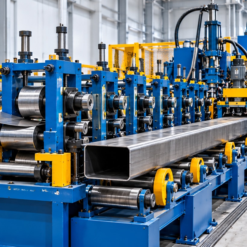
Direct forming means making a square or rectangular hollow section from flat strip without first producing a round tube and reshaping it. In square tube production and rectangular tube production, the strip follows this sequence:
- The decoiler unwinds the coil; entry guides centre it, and edge preparation removes burrs and prepares clean mating edges.
- Breakdown stands bend the strip progressively, followed by side-forming and corner-forming passes. Deformation concentrates in the corners, leaving more flat wall relatively undeformed.
- Fin passes close the profile and position the edges. High-frequency welding joins them, while non-round squeeze rolls, an impeder and scarfing system control the seam and remove weld flash.
- Sizing and calibration set width, height, corner radius and twist. A straightener corrects residual bow, then a flying saw cuts length; end finishing removes burrs before bundling and packaging.
The round-to-square method comparison is direct: conventional production first forms and welds a round tube, then uses an intermediate reduction section and associated stands to reshape it. Direct forming removes that section, but its four walls have different strain histories and need coordinated roll pressure, seam tracking and thermal control.
| Factor | Direct forming | Round-to-square |
|---|---|---|
| Layout and pass count | Shorter route; fewer reduction stands | Longer route with reshaping stands |
| Load and control | Corner-focused load; profile-specific calibration | Distributed reshaping load |
| Weld zone | Harder access; non-round rolls and tooling | Simpler round welding access |
| Tooling and changeover | Higher profile-specific investment; recipes or roll changes | More shared tooling; often quicker changes |
| Dimensional control | Excellent flats, sensitive corners and diagonals | Reshaping can distort walls and weld area |
Choosing a product window: section geometry, steel and production volume
Direct forming suits square and rectangular tube made in sustained volumes, especially where eliminating round-to-square reshaping improves output. Define the product window as outside width × height, tube size range, wall thickness range, corner radius, steel grades, yield strength range and production-speed range; require the supplier to state exact minimum and maximum values.
Calculate strip width from the developed perimeter plus weld and trim allowances, not by adding nominal outside dimensions. Thickness, corner radius, grade, roll geometry, scarfing and flash removal all change the allowance, so confirm it through trials.
Square and rectangular sections need different recipes. Rectangular tube requires control of flat-width stability, diagonal difference, torsional response and side-dimension ratio. Corner radius changes strain, thinning, section properties and downstream fit-up.
| Product or condition | Direct-forming position | Practical limit to verify |
|---|---|---|
| High-volume, narrow range | Strong fit | Confirm line speed and coil supply |
| Frequent changes or short runs | Weaker fit | Changeover time and tooling cost |
| Heavy or thin wall, high-strength grade | Possible | Forming force, springback and weld stability |
| Extreme aspect ratio, tiny radius or unusually thick wall | Risk case | Run representative trials |
| Incompatible welding or sizing equipment | Disqualifying | Check seam access and pass capability |
Before ordering, record:
- Annual tonnage, target line speed, coil weight, changeover frequency, floor space, utilities and operator skill.
- Cutting, bundling and handling requirements.
- The exact standard: EN 10219-1, EN 10219-2, ASTM A500/A500M, ISO 3394 where applicable, or the customer drawing.
Treat generic figures as screening data only. The final supplier must confirm dimensions, wall thickness, strip width, steel grades, yield strength and speed through trials.
Roll-pass design, strip preparation and weld control
A stable window starts with gradual transverse bending, not rapid profile closure. Set roll-pass geometry so breakdown passes distribute strip width, side-forming passes establish the walls, corner-forming passes build radius progressively, fin passes bring edges together, and sizing passes correct dimensions without excessive reduction.
Control longitudinal strain at every stand; closing too quickly creates edge waves, flat-side bow, twist, corner cracking and diagonal mismatch.
Calculate developed strip width from the section perimeter, corner geometry, weld upset and trim allowance. Align every roll to the pass line, then set roll gaps for actual thickness and grade. Use shared stands for compatible sizes; use dedicated rolls when aspect ratio, wall thickness or corner radius changes strain materially.
| Shared stands | Lower tooling inventory and faster size changes | Compatible sections with limited geometry variation |
|---|---|---|
| Dedicated rolls | Better repeatability and pressure control | Broad ranges, heavy wall or demanding corners |
Inspect slit edges, burr orientation, telescoping, camber, width tolerance and surface damage before loading. Set decoiler tension high enough to prevent wander, not high enough to stretch the strip.
Tune high-frequency power and frequency with vee angle, squeeze-roll pressure and impeder selection. Track the seam and control heat-affected-zone width; remove weld flash without gouging the parent metal. Use Turk-head adjustment for straightness, twist and diagonal difference.
Mill scale, oil, damaged edges, incorrect fin pressure or an unsuitable vee angle can cause lack of fusion, cold welds, excessive upset or hook cracks; overfill at corners, underfill on flats, weld-line offset and unstable welds expose the same narrow process window.
Tooling architecture, setup effort and total operating cost
Separate roll stands offer the easiest maintenance access but demand more roll-design work, pass-line alignment, crane handling and spare-roll storage. Conventional W-forming reduces forming complexity, while rafted cassette tooling improves repeatability by moving aligned stands as a unit.
| Arrangement | Strength | Cost and downtime effect |
|---|---|---|
| Separate stands | Flexible access and adjustment | Higher tooling cost, alignment time and spare-roll inventory |
| Rafted cassette tooling | Repeatable setup with stored pass-line geometry | Needs crane or handling space; cassette storage and maintenance access cost more |
| Cassette change systems | Fast size changes using prepared sets | Requires duplicate tooling and disciplined recipe control |
| Universal forming | Shared rolls with adjustable guides | Lowest inventory, but narrower section range and greater setup sensitivity |
Every size does not require a separate line. Section range, wall thickness, corner geometry, aspect ratio and seam position decide whether shared stands, adjustable guides or dedicated tooling remain stable. Universal forming becomes false economy when repeated adjustment damages repeatability or corner quality.
A real changeover means installing or loading rolls, aligning the pass line, setting roll gaps and guides, configuring the weld box, impeder, squeeze rolls and scarfing, calibrating sizing stands, running trial coils, inspecting samples and saving the approved recipe.
Budget beyond the mill: roll design and tooling inventory, spares, trial material, commissioning scrap, setup labour, floor space, utilities, inspection equipment, roll wear, weld-tool replacement, saw blades, coolant, impeder maintenance, alignment checks and lost production. Gallium Equipment Pvt.
Ltd. should be asked to price this architecture against your product window, not as a generic tooling package.
Related products
 | Tooling for Tube Mill & Slitting Line Tooling for Tube Mill & Slitting Line View product → |
 | CONVENTIONAL ERW TUBE MILLS/ CONVENTIONAL ERW TUBE MILLS/ RAFTED CASSETTE TYPE TUBE MILLS Gallium offers custom-made ERW HF Tube mills in both Conventional WForming Design and Cassette-type Rafted Design for rapid changeover which results... View product → |
Proving tube quality from commissioning through routine production
Commissioning acceptance requires a dimensional-control map, not one width reading. Record tube quality measurement at low, rated and maximum agreed speed, then compare each result with the customer drawing or specified standard.
| Control point | What to record |
|---|---|
| Outside section | Width, height and corner radius |
| Wall condition | Thickness variation and corner thinning |
| Geometry | Straightness, twist and diagonal difference |
| Weld | Seam position, weld integrity and bead or flash condition |
| Cut finish | Cut length, surface condition and saw-cut burrs |
Use at least five tubes per size, sampled across the start, middle and end of a coil. Keep dimensional inspection records, weld tests, surface checks and speed-trial results. Demonstrate every agreed size changeover, and obtain the spare-parts list, operator-training record and complete maintenance, setup and approved-recipe documentation.
Base acceptance on EN 10219-1, EN 10219-2, ASTM A500/A500M or the customer drawing. State the exact edition and grade in the quotation; nominal mill setpoints do not define compliance. Add a straightener after welding and sizing when residual bow or twist remains outside tolerance.
Excessive correction can flatten corners, alter diagonal difference and load the weld area.
Diagnose drift in this order:
- Check strip tracking and decoiler tension for wander.
- Verify fin-pass pressure, vee angle and seam tracking for weld instability.
- Inspect roll gaps and thermal conditions for dimensional drift.
- Review strip thickness and grade variation for inconsistent corner radius.
- Check guides, flying-saw synchronisation and support for high-speed defects, cut-length error, flattening and burrs.
Frequently asked questions
How does direct forming produce square and rectangular tube?
The mill progressively bends flat strip through forming stands, closes the edges for welding, and finishes the welded tube into its square or rectangular profile without first forming a round tube.
What should you evaluate before choosing a direct forming tube mill?
Define the section width, height, wall thickness, corner radius, steel grade, strip width range and required production volume before comparing mill designs.
Which controls have the greatest effect on tube quality?
Accurate strip preparation, roll-pass alignment, stable weld settings, controlled forming pressure and regular checks of dimensions and corner geometry protect quality.
How do tooling and setup affect operating cost?
Tooling architecture determines changeover time, storage requirements, adjustment work and the number of components exposed to wear, so compare total setup and maintenance effort rather than purchase price alone.