A tube can appear straight while still failing a local straightness limit, ovality requirement or surface-finish inspection. You will learn how the machine applies controlled bending, how to measure the result, how to choose settings for the tube, and how to separate machine-caused defects from incoming material variation.
Key takeaways
- Measure straightness over a defined length with a dial indicator.
- Match roll penetration and spacing to tube diameter and wall thickness.
- Use gradual bending to avoid surface marks, collapse and residual curvature.
- Check both ends and the middle to detect false straightness.
How adjustable rolls correct different tube defects
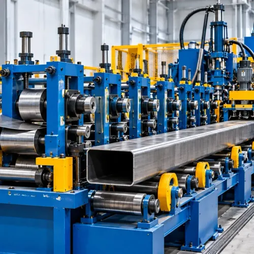
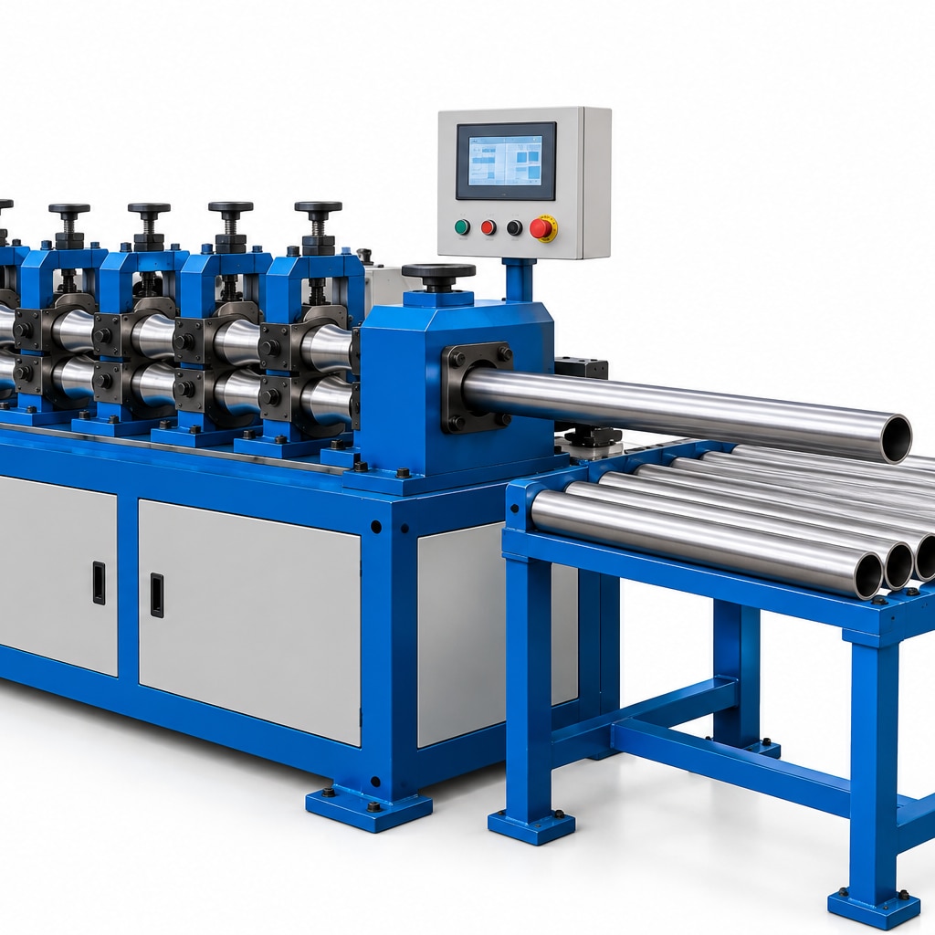
A rotary tube straightening machine corrects longitudinal shape by passing the tube through adjustable rolls that bend it in alternating directions. Support rolls control the tube between contacts; roll inclination, roll spacing, roll alignment, roll penetration and pass-line control determine where each bending load acts.
Selected zones pass beyond their elastic limit, leaving a counter-curvature that offsets the original bow.
| Defect | What the rolls address | Main limitation |
|---|---|---|
| Overall bow | Distributes correction along the tube length | A single setting may miss local deviation |
| Local bend | Concentrates correction through closer roll spacing and controlled penetration | Excessive force can flatten thin-wall tube |
| Camber | Corrects persistent side-to-side curvature through roll inclination and alignment | Poor alignment can create helical curvature |
| End bend | Uses end support and reduced local penetration | Unsupported ends can flare or remain bent |
| Twist | Can reduce slight rotational misalignment through roll alignment and seam orientation | Severe twist requires checking tube geometry |
| Ovality | Can be monitored while adjusting penetration | More penetration can increase flattening |
| Local dent | Usually bypasses or reduces its effect | A severe dent needs repair or rejection, not straightening |
Roll displacement cannot simply equal the required correction because the tube springs back after unloading. Yield strength, wall thickness, prior cold work and contact spacing change that recovery, so adjust in small steps and measure the result.
Straightening corrects longitudinal shape, not major wall-thickness variation, eccentricity, unstable weld geometry or severe local dents. Those conditions alter bending response and leave residual dimensional error even when the average tube appears straight.
How to measure straightness, ovality and dimensional accuracy
A repeatable tube straightness measurement uses the same datum, support spacing, gauge lengths and tube condition for incoming and outgoing inspection. For a basic check, place the clean tube on a clean surface plate, support it on two V-blocks at a recorded spacing, and use a calibrated dial indicator against a defined reference line.
- Record tube length, outside diameter, wall thickness, weld-seam orientation and inspection condition. Rotate the tube through 360 degrees and record the high spot rather than measuring one arbitrary face.
- Traverse the dial indicator over the full tube length and record maximum deviation from the reference line. Repeat the reading over a stated local gauge length, such as the drawing’s specified length, and measure the end region separately.
- Measure outside diameter at several positions along the tube and at two perpendicular axes at each position using a calibrated micrometer, laser gauge, or bore-and-outside-diameter system. Calculate ovality as the difference between the maximum and minimum measured diameters at each cross-section.
- For continuous production, use laser measurement of tube straightness or a vision system, but define its datum, sampling interval and filtering rule before comparing results.
“Straight within 2 mm” is incomplete: state whether 2 mm applies over the full length or a local gauge length, identify the datum, tube condition and acceptance rule. Keep straightness separate from outside diameter, wall thickness, end squareness, ovality and surface-finish tolerances. A tube can be straight and still fail the drawing.
How to set rolls for diameter, wall thickness and material strength
Build tube straightening settings from measured deviation and product response, not from nominal roll position. Record outside diameter, tube wall thickness, diameter-to-wall-thickness ratio, tube length, yield strength, material condition, weld-seam orientation and initial bend severity. Higher-strength or cold-worked tube needs greater force and more springback allowance than mild steel.
- Set roll diameters, roll spacing, inclination, alignment and pass-line offset to support the tube without forcing its section out of shape. Count the effective bending contacts; fewer contacts require more correction at each contact, while more contacts distribute correction across additional straightening passes.
- Start with the minimum roll penetration that removes the measured deviation. Adjust feed speed to maintain stable contact, especially on long or thin-wall tube.
- Check straightness and ovality after every effective pass. Increase roll penetration in small, recorded steps only when the result remains outside the drawing limit.
- Stop and reset the setup if the tube develops end flare, alternating or helical curvature, wall-thickness distortion, wrinkling, buckling or roll marks.
Thin-wall tube has little tolerance for aggressive local bending, so gradual correction and accurate support matter more than rapid bow removal. Higher-strength material can spring back after unloading, but extra penetration is not a safe substitute for controlled force.
Keep the setup record with roll diameters, pass-line offset, feed speed, material heat or batch, pre-process measurements and post-pass results. Record the final penetration and number of effective contacts so the next batch starts from evidence rather than memory.
Which straightening process fits the tube and production requirement
Choose the process by the tube’s product envelope and tolerance, not by outside diameter alone. For welded and seamless tube straightening, the wrong method can remove bow while leaving ovality, marks or a local bend.
| Option | What it does | When it fits |
|---|---|---|
| Rotary straightening | Uses repeated roll contacts for continuous correction; set seam orientation and bead height. | Welded or seamless tube, production lines and controlled straightness. |
| Pressure straightening | Applies force at selected locations to remove a known bend. | Discrete correction, with firm support to prevent local dents. |
| Draw straightening | Pulls tube through a controlled die or straightening arrangement. | Drawn precision tube when surface contact and dimensional change are acceptable. |
| Sizing | Controls outside diameter and shape through tooling. | Diameter correction; it is not a replacement for correcting longitudinal bow. |
Check these selection criteria before specifying the machine:
- Diameter-to-wall-thickness ratio and yield strength, because thin-wall or high-strength tube responds differently to roll force.
- Tube length, initial bend severity, allowable ovality and straightness tolerance.
- Seam condition, bead removal, weld-zone hardness and required seam orientation.
- Coating or surface requirement, since contact marks can disqualify an otherwise straight tube.
- Required line speed and the number of effective correction contacts.
Ask each machinery supplier for a capability trial using your actual tube. Require measured before-and-after straightness and ovality, roll wear compensation, and a written acceptance record tied to your drawing limits. Gallium Equipment Pvt. Ltd. is relevant when comparing integrated steel-tube equipment against those results rather than choosing by diameter alone.
Related product
 | Pipe straightening Machine plays a vital role in improving the quality of ERW,SS Tubes being produce on Tube Mills & Draw Benches and after annealing... View product → |
How to prevent marks, collapse and false straightness
Start with the same straightening machine inspection sequence for every suspect tube: compare pre-process and post-process bow, local deviation, ovality, wall thickness and end condition at identical gauge lengths. A single end-to-end reading can hide alternating bends or a locally collapsed section.
1. Inspect every roll for pickup, chips, grooves, contamination and diameter wear. Repeated roll marks and scratches that match the longitudinal or circumferential contact pattern identify tooling as the source, not the tube surface.
2. Check roll alignment and pass-line height when the tube shows helical curvature, alternating bends, or a straight average with poor local readings. A small alignment error can create residual curvature that the average measurement misses.
3. Reduce penetration and verify tube support when tube collapse and ovality, wrinkling or end flare increase. Straightening cannot replace sizing when diameter, wall thickness or eccentricity varies substantially.
4. Check seam orientation, bead removal and weld-zone hardness when damage follows the weld line. The weld changes bending stiffness and roll contact.
5. Confirm the material batch and incoming geometry before changing the recipe if results vary along one tube or between tubes.
| Defect pattern | Check first | Corrective action |
|---|---|---|
| Repeated surface lines | Roll condition and cleanliness | Clean, regrind or replace the roll |
| Helical or alternating bends | Alignment and pass-line height | Realign and verify with local readings |
| Flattening or wrinkling | Penetration and support | Reduce penetration and improve support |
| Weld-line damage | Seam and bead condition | Reorient or prepare the weld zone |
Accept after unloading and after cutting, welding, stress relief or temperature equalisation when those operations can release residual stress. Record settings, roll condition, measurements and drawing limits.
Frequently asked questions
How do adjustable rolls correct tube defects?
Rolls bend the tube in alternating directions. Roll inclination, spacing, alignment, penetration and pass-line height control the location and severity of each correction.
How do you measure tube straightness and ovality?
Measure runout along a defined tube length with a dial indicator, then measure outside diameter at multiple points around the circumference and along the tube.
How should rolls be set for tube diameter, wall thickness and material strength?
Set the pass line and roll spacing first, then apply controlled penetration. Thin-wall or high-strength tubes need smaller correction increments to limit collapse and permanent marks.
How can you prevent marks, collapse and false straightness?
Align the rolls, keep contact pressure uniform, clean the tooling, use gradual settings and inspect the tube at several positions instead of checking only one section.