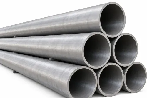
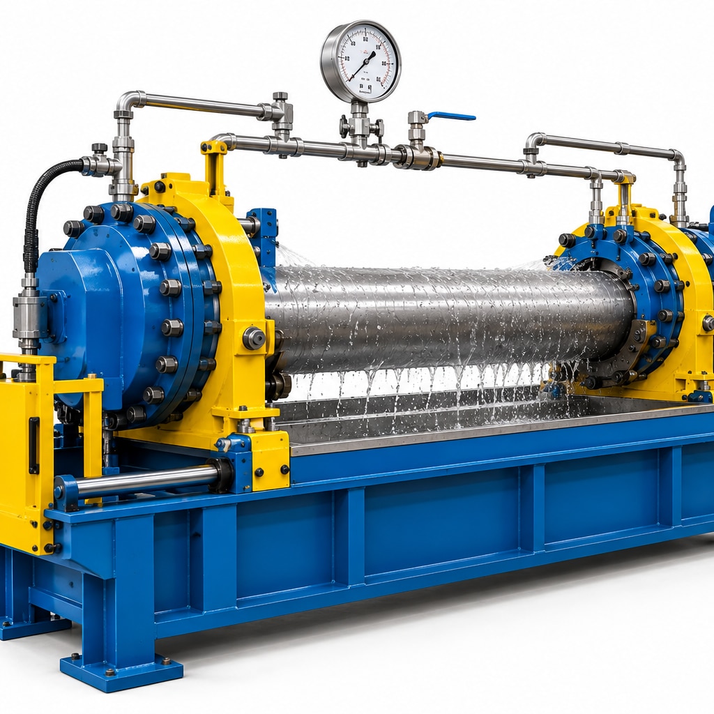
A dependable pipe pressure test depends on more than a pump reaching a high number: trapped air, end seals, pressure measurement, hold-time control and safe depressurisation all affect the result. You will be able to define the test, choose a suitable machine configuration and identify the records and safeguards needed for a defensible pass or fail decision.
Key takeaways
- Remove trapped air before raising test pressure.
- Set pressure and hold time from the pipe specification or test standard.
- Match pump capacity, end closures and controls to your pipe range.
- Record pressure, hold time, leakage observations and final disposition.
What happens during a hydrostatic pipe test?
Fill the pipe completely with water, remove trapped air, then raise pressure with a pump to the value specified for that pipe. Hold it for the required time while checking for visible leakage, pressure loss and distortion.
The applicable product standard, purchase specification, material grade, wall thickness and end-condition limits set the test pressure; the machine’s pressure rating does not. A gauge one metre above or below the pipe can differ by about 0.098 bar because of water head. Allow for this in long or vertical test arrangements.
Pressure may also change as the pipe wall, seals and trapped gases stabilise, so do not treat an immediate drop as proof of a leak.
A typical sequence is:
- Fill and vent the pipe until no air pockets remain.
- Increase pressure in controlled steps.
- Stabilise, hold and inspect the pipe, welds, closures and connections.
- Depressurise, drain and dry the pipe, especially carbon steel or chloride-sensitive stainless steel.
| Test type | What it measures | Main difference |
|---|---|---|
| Hydrostatic pressure test | Pressure containment and through-wall leakage using water | Low stored energy; suited to production pipe testing |
| Leak test | Leakage at a specified pressure | Focuses on tightness, not necessarily structural strength |
| Burst test | Pressure at which the pipe ruptures | Destructive qualification test |
| Pneumatic test | Pressure containment or leakage using compressed gas | Faster and cleaner, but stores far more hazardous energy |
Hydrostatic testing does not replace weld, lamination, dimensional or material inspection.
How do you set test pressure and acceptance criteria?
Pressure for a specific pipe comes from the governing product and purchase requirements, not the machine’s maximum rating. Identify whether API 5L, API 5CT, ASTM A53 or ASTM A500 applies, then confirm the specified pressure for that edition, grade, diameter, wall thickness, weld condition and end preparation.
If ASME B31.3 or a customer specification controls the test, use its stated basis.
Set the recipe in this order:
- Fill and vent the pipe completely; trapped air compresses and distorts the pressure response.
- Raise pressure with a controlled final-approach stage. A high-flow pump can overshoot the set point before the shutoff valve responds.
- Hold for the exact duration specified for that pipe and standard. Do not replace it with a universal 30-second or five-minute setting when the product changes.
- Accept the pipe only against the stated criteria: no visible through-wall leakage, no prohibited deformation and a pressure-time trace within permitted limits.
Use a calibrated pressure transducer or recorder alongside the local gauge. Record the pipe identity, set pressure, actual hold time, sensor identity, calibration status, recipe, operator or station, interruptions, pressure excursions and reject disposition. A green signal alone cannot distinguish a pipe leak from fixture leakage, pressure overshoot or an instrument fault.
Which machine configuration fits your pipe range and production rate?
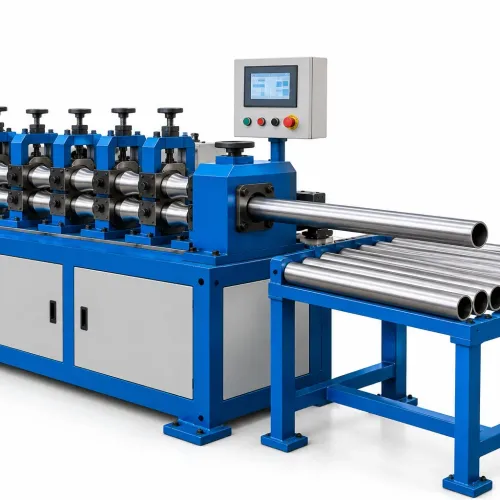
Choose the machine around your pipe outside-diameter range, end condition, sealing method and required cycles per hour—not around pump pressure alone. A broad product mix needs adjustable tooling; a narrow, stable range rewards dedicated heads and faster handling.
| Configuration | Best fit | Sealing and end preparation | Throughput effect |
|---|---|---|---|
| Batch, adjustable | Several diameters and short runs | Interchangeable test heads; threaded seals for prepared threads or expanding seals for suitable plain ends | More changeover time, lower sustained rate |
| Dedicated station | One diameter family and repeat orders | Fixed heads and seals matched to the actual bore, ovality and wall | Shorter setup and consistent cycles |
| Multi-station or inline | High volume with stable dimensions | Automated end loading, clamping and seal verification | Parallel filling and testing reduce waiting between pipes |
Treat burrs, weld-bead geometry, scale, ovality and end squareness as machine-selection data. A nominal diameter alone cannot prevent seal extrusion or fixture leakage. Include the complete cycle: loading, filling, air removal, pressurisation, hold, depressurisation and unloading.
Closed-end testing creates axial thrust. Use F = PπD²/4 as the idealised starting point; doubling diameter increases this component about fourfold. Rate the frame, locking system, manifolds, hoses, valves and test heads together, and define separate maximum allowable working and test pressures for each tooling setup.
Give Gallium Equipment Pvt. Ltd. the full diameter, wall-thickness, end-preparation and hourly-output schedule before comparing machine layouts; those details expose whether the bottleneck is pumping, sealing or handling.
What equipment and safeguards belong in the pressure-test circuit?
A complete pressure-test circuit needs separate filling, pressurising, measuring, isolating and safe-release functions. Use a filling pump for rapid water displacement, then a lower-flow high-pressure pump for the controlled approach to pressure; using the filling pump for final pressurisation can overshoot the set point.
- Install a high-point air vent and a low-point drain. Trapped air stores energy and produces unstable readings.
- Fit non-return valves to stop reverse flow and isolation valves to separate the pipe, pump and gauge during inspection.
- Connect a pressure transducer to a recorder, alongside a local calibrated pressure gauge. The gauge supports immediate operator awareness; the transducer captures hold time, stabilisation and pressure excursions.
- Use end closures, test heads, manifolds, hoses and quick couplers rated for the complete pressure boundary, including pressure cycling.
- Restrain the pipe and closures against thrust. Do not rely on clamps or fixtures whose rating is lower than the circuit rating.
- Add a relief valve, guarded test zone, remote start, emergency stop and controlled depressurisation valve.
| Control | Purpose | Failure prevented |
|---|---|---|
| Relief valve | Limits pressure above the defined machine setting | Overpressure after valve-response delay |
| Interlock | Blocks pumping with an open guard or unseated head | Ejection during pressurisation |
| Drain valve | Releases pressure before opening the circuit | Stored-energy injury |
| Pressure recorder | Links pressure and time to the test record | Unprovable acceptance decision |
Define a maximum allowable working pressure and a separate maximum test pressure for each tooling configuration. Account for gauge elevation: water adds about 0.098 bar per metre of height difference.
How do you verify, record and interpret the final test result?
A falling pressure reading is not enough to call a pipe leaking. Complete filling and air removal, allow the defined stabilization period, then start the timed hold; pressure decay during stabilization can result from water-temperature change, pipe-wall expansion, seal movement or trapped-air dissolution.
Use the time-pressure trace to separate those effects from a failure:
- A smooth early decline that levels off before the hold begins indicates stabilisation, not a failed pipe.
- A continuing decline during the acceptance hold, especially with visible wetting, identifies a leak path.
- A sudden step change points to fixture leakage, valve movement, hose failure or an interrupted test; stop safely and inspect the pressure boundary only after depressurisation.
- Isolate the pipe from the end closures and repeat the check with a blank, calibrated reference piece or fixture-only pressure test. If the fixture loses pressure, do not reject the pipe.
A calibrated pressure transducer and data logger provide stronger evidence than the local gauge alone. Save the trace showing fill, stabilisation, hold time, pressure excursions and final result.
For test traceability, link the record to the pipe or heat number, test pressure, hold time, sensor identity and calibration due date, machine recipe, operator or station, and reject disposition. Record the applicable acceptance clause, such as ASME B31.3, plus the reason for any retest or override.
Frequently asked questions
What happens during a hydrostatic pipe test?
You fill the pipe with water, remove trapped air, raise pressure with a pump, hold it for the specified time, and inspect for leakage, pressure loss and distortion.
How do you set test pressure and acceptance criteria?
Use the pipe specification, purchase order or named test standard to set pressure, hold time, allowable pressure change and visible-leakage limits before testing.
Which machine configuration fits your pipe range and production rate?
Select the pump, end closures, water circuit, controls and handling arrangement according to pipe diameter, length, pressure, material, test cycle and required throughput.
What equipment and safeguards belong in the pressure-test circuit?
Use rated end closures, a calibrated pressure gauge or transducer, fill and drain valves, air-release points, relief protection, guarding and a controlled operator position.
How do you verify, record and interpret the final test result?
Compare the recorded pressure and hold time with the approved criteria, document leakage or distortion observations, and identify the pipe, machine and test result.