A failed tube thread does not prove that the cutter caused the defect. Start by isolating the machine and preserving the evidence, then compare the tube, tooling, workholding, motion system and gauges before changing settings. By the end, the reader will have a recovery sequence, a maintenance schedule and clear criteria for releasing, servicing or replacing the machine.
Key takeaways
- Quarantine suspect tubes and preserve the failed tool before cleaning or replacement.
- Measure tube, tooling and workholding faults instead of guessing at the cause.
- Set maintenance intervals from recurring failures, chip buildup and alignment checks.
- Release production only after a conforming trial piece passes inspection.
1. Isolate the failure and inspect the tube before touching the cutter
1. Stop the threading machine, isolate it from production, and quarantine every suspect tube from the affected lot. Apply the site’s lockout/tagout procedure before entering the danger zone or handling hazardous energy. Preserve the failed parts, one acceptable sample, and the tool exactly as found; do not replace or clean the tool before inspection.
2. Record the tube size, grade, wall thickness, heat or batch number, thread standard and designation, operator, machine settings, tool identity, defect photographs, alarm codes, gauge readings, and any replaced components. This record is the foundation of threading machine maintenance for tubes.
3. Compare an unthreaded tube and a threaded tube from the same lot. Before adjusting the threading head, measure OD, ID, wall thickness, ovality, straightness, end squareness, burrs, chamfer angle, chamfer diameter, end flare, weld-bead intrusion, local wall variation, and tube curvature. An upstream end defect can make a sound cutter appear faulty.
4. For ERW tube, apply a documented weld-seam orientation rule and verify the seam’s position. Inspect whether it is proud, inconsistently ground, or loading the insert. A damaged thread can result from tube geometry, seam condition, workholding, tooling, or measurement; the same visible defect does not prove one cause.
These records narrow the fault tree before any adjustment.
2. Separate tooling, workholding and machine faults with measured checks
1. Inspect the die or insert before changing settings. Look for wear, chips, thermal cracks, blunt edges, built-up edge, incorrect thread geometry, wrong tool height, damaged seats, and poor chip evacuation. Confirm cutting speed, feed, coolant direction and flow; long chips can wrap around the tube, obstruct coolant and pull alignment off.
These checks explain incomplete or damaged threads, burrs, chatter, overheating and tool breakage.
2. Check workholding next. Inspect chuck or collet wear, jaw alignment, clamping pressure and repeatability, contamination on gripping surfaces, tube-wall collapse, unsupported length, ovality and runout. A thin-wall tube can distort under pressure and spring back after release, creating slippage or a defect that disappears during inspection.
3. Put a dial indicator on the clamping zone and use a test mandrel to check spindle, toolholder, tail support and axial movement. Measure feed-mechanism backlash. Inspect guideways, lead screws, bearings, gears, belts, couplings and guards for taper, misalignment, abnormal noise or unexpected stoppage.
4. Use the specified thread plug gauge and thread ring gauge, then a pitch gauge and caliper or micrometer. Compare results to separate pitch, form, taper and pitch-diameter errors, including oversize or undersize conditions. Inspect coolant lines, filters, pumps, electrical cabinets, sensors, limit switches and emergency-stop circuits.
One symptom never proves one failed component; require measurement or inspection evidence before assigning these tube threading machine problems to tooling, workholding or the machine.
3. Build a maintenance schedule around the causes that repeat
A useful threading machine maintenance schedule follows recurring failure modes, not a generic calendar. Record each check against the tube lot, grade, wall thickness and seam condition.
- Every shift, remove chips from the work zone and guideways. Inspect guards and emergency-stop function; check coolant level, concentration, contamination, tramp oil, filter condition, nozzle alignment and delivery pressure. Record tool identity, ends cut and thread gauge results.
- Weekly, clean coolant lines and the chip-control area. Inspect chuck or collet jaws, belts, couplings, fasteners, sensors, limit switches and visible leaks. Verify every lubrication point against the machine builder’s lubricant type, quantity and interval.
- Monthly, measure spindle and workholding runout with a dial indicator and check feed backlash. Inspect lead screws, bearings, gears and guideways; verify gauges against their calibration status. Review rejection mode by tube lot, grade, wall thickness and seam condition.
- During a planned overhaul, inspect spindle bearings, toolholder seats, feed mechanisms, electrical cabinets, pump and filtration performance, alignment and guard circuits.
Over-lubrication contaminates thread surfaces and coolant, while under-lubrication causes slide stiction, positioning error and bearing damage. Record lubricant type, quantity, point and date rather than writing “oiled.”
Track tool life by thread inspection and cutting load, not machine hours alone. Record progressive flank wear, chipped inserts, built-up edge, thermal cracking, speed, feed and ends cut; these changes can alter pitch diameter and flank form before visible tool failure.
4. Correct the root cause, validate the trial piece and release the machine safely
Quarantine suspect production and locate the defect’s starting point and direction before cutting again. Check tube preparation and seam control, including end squareness, flare, ovality, weld-bead intrusion and wall variation. Repair workholding or alignment, replace or reset tooling, clear chips, restore coolant delivery, and document every parameter change.
Re-cut only when thread allowance and tube condition pass inspection. Change tooling for proven wear, damage or wrong geometry; adjust speed or feed for a measured cutting-data cause; complete broader repair for runout, backlash, slippage, structural damage or unsafe guarding. Preserve every previous setting instead of repeatedly changing inserts, speed and feed.
That discipline is threading machine maintenance for tubes, not guesswork about tube threading machine problems.
Acceptance comes from the drawing, purchase order or named standard, never a universal tolerance. For ASME B1.20.1 NPT, verify profile, pitch, taper, standoff and specified gauges. For API 5B connections, use required API gauging and dimensional controls. Check crest truncation, burrs, flank finish, lead, thread compound or sealant, and assembly or sealing requirements.
| Option | Use it when | Do not release on it alone |
|---|---|---|
| Re-cutting | Allowance and tube condition pass | Damaged or structural tube |
| Tooling change | Wear, damage or geometry is proven | Misaligned spindle |
| Speed or feed adjustment | Cutting data caused the defect | Repeated guesswork |
| Broader repair | Alignment, workholding or safety fault exists | Unverified machine state |
Release only after a documented trial piece passes the specified thread plug and ring gauges and dimensional checks. Stop for safety-critical or structural defects; qualified personnel must handle electrical, guarding, spindle and pressure-related repairs.
5. Decide when industrial service or replacement is justified
Operator adjustment has ended when taper, backlash, spindle damage or misalignment returns after documented tooling and tube checks. Escalate to industrial threading machine service for unexplained alarms, failed emergency-stop circuits, obsolete controls, or any defect that reappears after settings are restored.
| Option | Cost or risk to compare | Decision signal |
|---|---|---|
| Continue adjustment | Scrap, downtime, replacement parts and lost capacity | Reject only when a measured, repeatable correction remains available |
| Service inspection | Inspection fee and planned downtime | Choose when the root cause is uncertain or repairable |
| Replace machine | Capital cost, installation and commissioning | Replacement gains weight when the spindle train, controls or structural alignment need extensive work and parts are unavailable |
Do not approve a repair from “tool changed” as the only record. Require the manufacturer or service provider to supply:
- A written scope and inspection report identifying the root cause and corrective action
- Spindle and chuck runout measurements, alignment and calibration results
- Replacement-part provenance, settings used, gauges applied and trial-piece results
- Trial-run evidence, warranty terms and preventive-maintenance recommendations
The recovery record should show quarantined production, defect location and direction, tube checks, workholding and spindle findings, tool and coolant conditions, and the calibrated first-piece results. Repeatedly changing inserts, speed or feed without preserving previous settings destroys the evidence needed to find the fault.
Gallium Equipment Pvt. Ltd. is worth considering when you need a machinery manufacturer familiar with tube-forming systems and associated tooling; judge the engagement by these documented technical deliverables, not by the proposed repair alone.
Related products
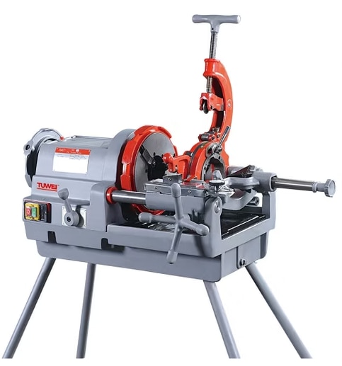 | Tube Threading Machine The Tube Threading Machine from Gallium Equipment Pvt. Ltd. is engineered for accurate and efficient threading of steel tubes used in industrial and... View product → |
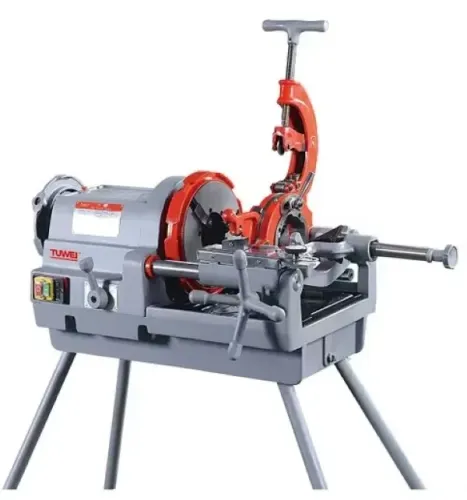
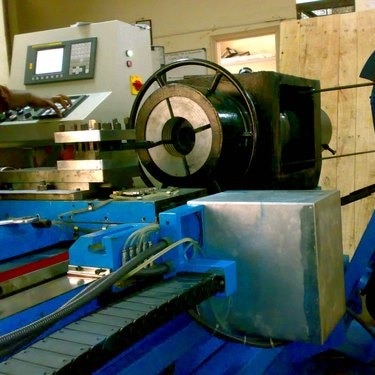 | We have full range of pipe threading machine, manual pipe threading machine, electric pipe threading machine, conduit electrical pipe threading... View product → |
Frequently asked questions
What should you do first after a tube threading failure?
Stop and isolate the machine, apply lockout/tagout, quarantine the affected lot, and preserve failed and acceptable samples with the tool unchanged.
How can you distinguish tooling, workholding and machine faults?
Use measured checks on thread dimensions, tube condition, tool wear, clamping, alignment, runout and machine movement to identify the fault source.
What should a threading machine maintenance schedule include?
Base inspections on recurring causes and specify checks for tooling condition, chip removal, lubrication, clamping, alignment, runout and safety systems.
When can you release a threading machine after repairs?
Run a controlled trial piece, verify its thread and tube dimensions against the drawing or specification, document the result, and remove the machine from hold only after acceptance.
Keywords