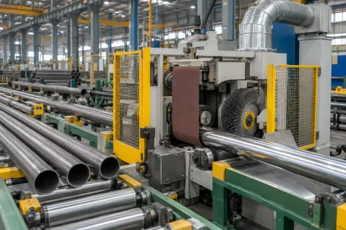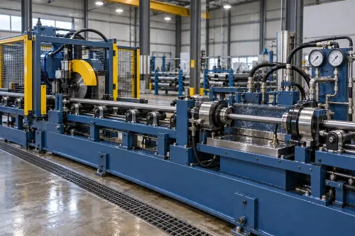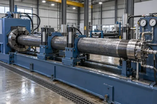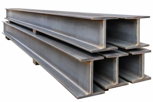
Architectural tubes must do more than meet a nominal width, height or diameter: they must fit connectors, produce clean joints and present an even visible surface. By the end, you will know where sizing and end finishing belong in production, which machine suits each operation, and what to specify before requesting equipment or quotations.
Key takeaways
- Use sizing to control dimensions, corner radius, flat faces, squareness and twist.
- Match end finishing to the joint: cut, deburr, bevel, swage, notch or form.
- Choose a draw bench for reduction; use mill stands for continuous calibration.
- Specify section sizes, tolerances, material, weld condition, throughput and inspection tests.
What sizing means for architectural tube geometry
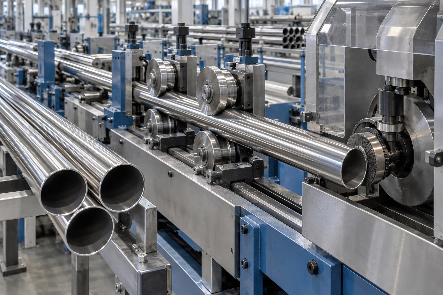
Sizing is controlled calibration after tube forming and welding. A sizing machine for architectural tubes brings outside dimensions to target, controls roundness in round sections and squareness in square or rectangular sections, and corrects flat-face width, corner radius and twist.
It prepares the section for polishing, coating or assembly; it does not create the profile or replace cutting and end finishing.
A sound specification names:
- The product standard: ASTM A500/A500M, EN 10219 or EN 10305
- The grade and wall thickness
- The outside diameter, or section width and height
- The corner-radius range, straightness and twist limits
- The weld-seam condition and surface finish, including polishing or coating requirements
- The cut-length and end-squareness tolerances
These standards cover defined tube products, not a universal architectural finish. Architectural tube is a market description, so the order must state the appearance and surface limits separately. A sizing and end finishing machine for architectural tubes must therefore be selected for the complete geometry, not width and height alone.
Visible sections in handrails, balustrades, stair components, canopy frames, furniture, display systems and façade members expose every flat-face variation, uneven corner and scratch.
A structural tube that performs adequately under load can still fail an architectural inspection because the corner radius changes along its length, twist misaligns a joint, or a surface defect remains visible after polishing or coating.
Where sizing fits in the architectural tube production sequence
Sizing belongs after ERW forming and welding because the sizing machine for architectural tubes calibrates a section that already exists; it does not create the square or rectangular profile. It also cannot cut length or perform end finishing.
1. Form strip through forming stands, weld the seam, and inspect weld quality. Record whether the bead remains, is externally scarfed, internally scarfed, or scarfed on both sides.
2. Pass the welded tube through sizing stands. Roll alignment and pass calibration control width, height, corner radius, squareness, straightness and twist, but sizing cannot erase strip-width variation, roll misalignment, springback, temperature, residual stress or changing weld-bead height.
3. Cut to length, then straighten the pieces. Keep section checks separate from end checks: measure width, height, wall thickness, corner radius, straightness and twist, then verify length, end squareness, burr height and surface defects.
4. Apply end finishing after sizing and cutting. Facing, squaring, deburring, chamfering, reducing, expanding, swaging, beading, threading, slotting and notching serve different assembly functions; sizing cannot replace the cutting equipment or end-finishing line.
5. Specify internal scarfing when a tube must telescope, pass over a mandrel, or retain a clear internal passage. A protruding internal bead can block insertion even when outside dimensions are correct.
6. Change the sequence for downstream processes: drawing becomes the dimensional-reduction operation, annealing restores ductility when the reduction schedule requires it, and polishing or coating follows earlier decisions about weld condition and surface quality.
Which end-finishing operation matches the joint
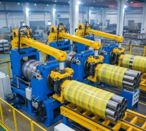
Choose the end operation from the joint function, not from the tube’s nominal width, height or diameter. An end finishing machine for steel tubes prepares the cut end for assembly, coating or connection; it does not replace sizing, forming or cut-to-length equipment.
| Operation | Joint or assembly purpose | Typical result |
|---|---|---|
| Facing and end squaring | Repeatable length, butt joints and mitre fit | A flat end perpendicular to the tube axis |
| Deburring and chamfering | Safe insertion, clean handling and coating coverage | Burr-free edges with an entry lead |
| End reducing, expanding and swaging | Stepped joints, sleeves and connector transitions | A smaller, larger or locally shaped end |
| Beading | A formed stop for a sleeve, insert or clamp | A raised circumferential bead |
| Threading | Threaded fittings, nuts or screw connections | External or internal threads |
| Slotting and notching | Brackets, intersections and frame connections | A defined opening or shaped cut-out |
A tube can meet its cut-length tolerance and still leave a visible gap in a mitred handrail if the end is not square to its axis. Inside and outside burrs can prevent clean insertion, cut seals or leave coating holidays around the edge.
Threading solves only a threaded-joint requirement; it is not a substitute for facing, chamfering, notching or other end preparation.
Square and rectangular sections need tooling matched to their geometry. Dedicated punches, dies, internal supports or rotary tools prevent corner collapse and face bulging; round-tube tooling can distort both. Specify the joint, wall thickness, corner radius and required end location before selecting the machine.
Sizing machine, draw bench or tube-mill stand: choosing the process
A tube-mill sizing stand continuously calibrates a formed tube in-line, while a draw bench pulls a prepared cut tube through a die. The right choice depends on whether you need continuous geometry control or a discrete dimensional reduction.
| Machine | Change made | Best fit |
|---|---|---|
| Tube-mill sizing stand | Calibrates a formed tube continuously after welding | High-volume ERW production |
| Sizing machine for architectural tubes | Controls outside dimensions, flat-face width, corner radius and twist | Square and rectangular sections requiring consistent visible geometry |
| Straightening machine | Corrects bow and residual deviation without reducing section size | Tubes that meet section dimensions but fail straightness |
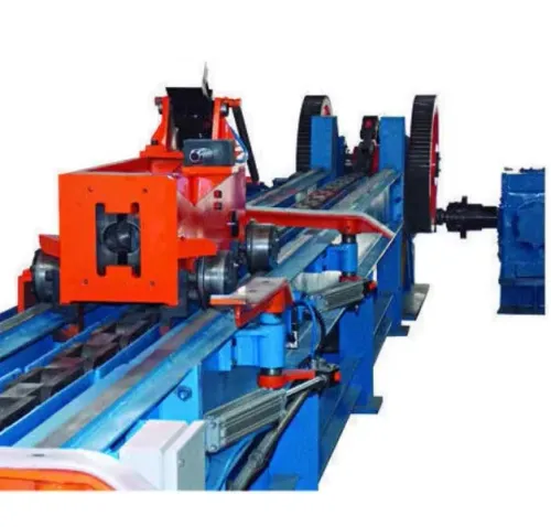
| Draw bench | Pulls cut tube through a die, with or without a mandrel, reducing section size and improving tolerance and surface finish | Precision rounds, special profiles and custom calibrated hollow sections |
Draw bench machine applications include tight-tolerance round tubes, unusual profiles and hollow sections that roll sizing cannot produce economically. Drawing is slower because it uses batch or semi-continuous handling, and each tube needs a prepared or pointed end that can enter and grip the die without splitting, buckling or galling.
Die wear and lubrication affect surface quality. Excessive reduction raises work hardening and reduces ductility, so divide the reduction across multiple draws and specify intermediate annealing when the grade and schedule require it. Do not promise a single-pass reduction without defining wall thickness, die angle, mandrel condition and lubrication.
Choose another process when you have:
- High-volume continuous ERW production
- Loose dimensional tolerances
- Short cut lengths
- A profile that cannot pass through a die
- A tube already in tolerance that needs only end preparation
What to specify, measure and verify before buying the line
Before buying a sizing and end finishing machine for architectural tubes, issue a machine brief that states the finished geometry, appearance and output—not just “40 × 40 mm tube.”
1. Define the product envelope: section width and height or outside diameter, wall thickness, steel grade, corner-radius range, weld-seam position, weld-bead condition, straightness, twist and permitted surface-finish defects. State whether the line must run polished, coated or assembly-ready tube.
2. Define production: cut-length tolerance, target production rate, bundle or batch length, and the number of open-size families. Record every size family, because changing a corner radius or section size generally requires different sizing rolls, not only a speed adjustment.
3. Specify the complete geometry for tooling selection. Roll alignment and pass calibration must control flat-face width, corner radius, wall distribution and twist together; nominal roll dimensions alone cannot do that. Check strip-width variation, springback, temperature, residual stress, weld-roll alignment and weld-bead height, because sizing cannot erase every upstream error.
4. Separate acceptance checks into section and end records. Section checks cover width, height, wall thickness, corner radius, straightness and twist. End checks cover length, squareness, burr height, notch or slot position, weld condition and surface defects.
Gallium Equipment Pvt. Ltd. can help convert these criteria into sizing rolls, end-forming tooling, inspection points and a line sequence, rather than treating a general tube machine as universal. Confirm whether the end finishing machine for steel tubes faces, squares, deburrs, chamfers, reduces, expands, swages, slots or notches the specified section.
Frequently asked questions
What does sizing control in architectural tube production?
Sizing calibrates the tube after forming and welding, controlling outside dimensions, roundness, flat-face width, corner radius, squareness and twist.
Where does sizing fit in the architectural tube production sequence?
Sizing follows tube forming and welding, then precedes operations such as cutting, straightening, inspection and end finishing when the joint design requires it.
How do you choose an end-finishing operation for a tube joint?
Select the operation from the joint requirement: cut and deburr for a plain butt joint, bevel for welding, and notch, swage or form for interlocking or fitted connections.
When should you choose a sizing machine, draw bench or tube-mill stand?
Use a sizing machine for post-forming calibration, a draw bench for controlled reduction or tight dimensional correction, and tube-mill stands for continuous in-line sizing.
Keywords