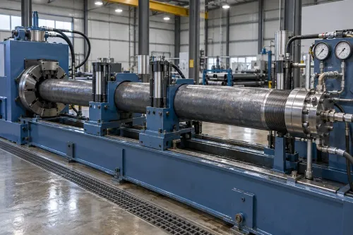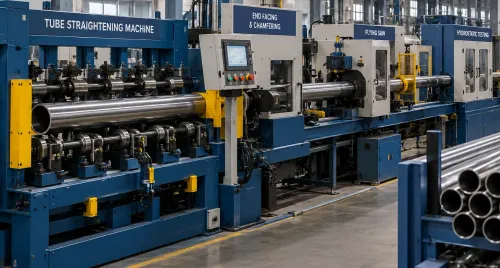
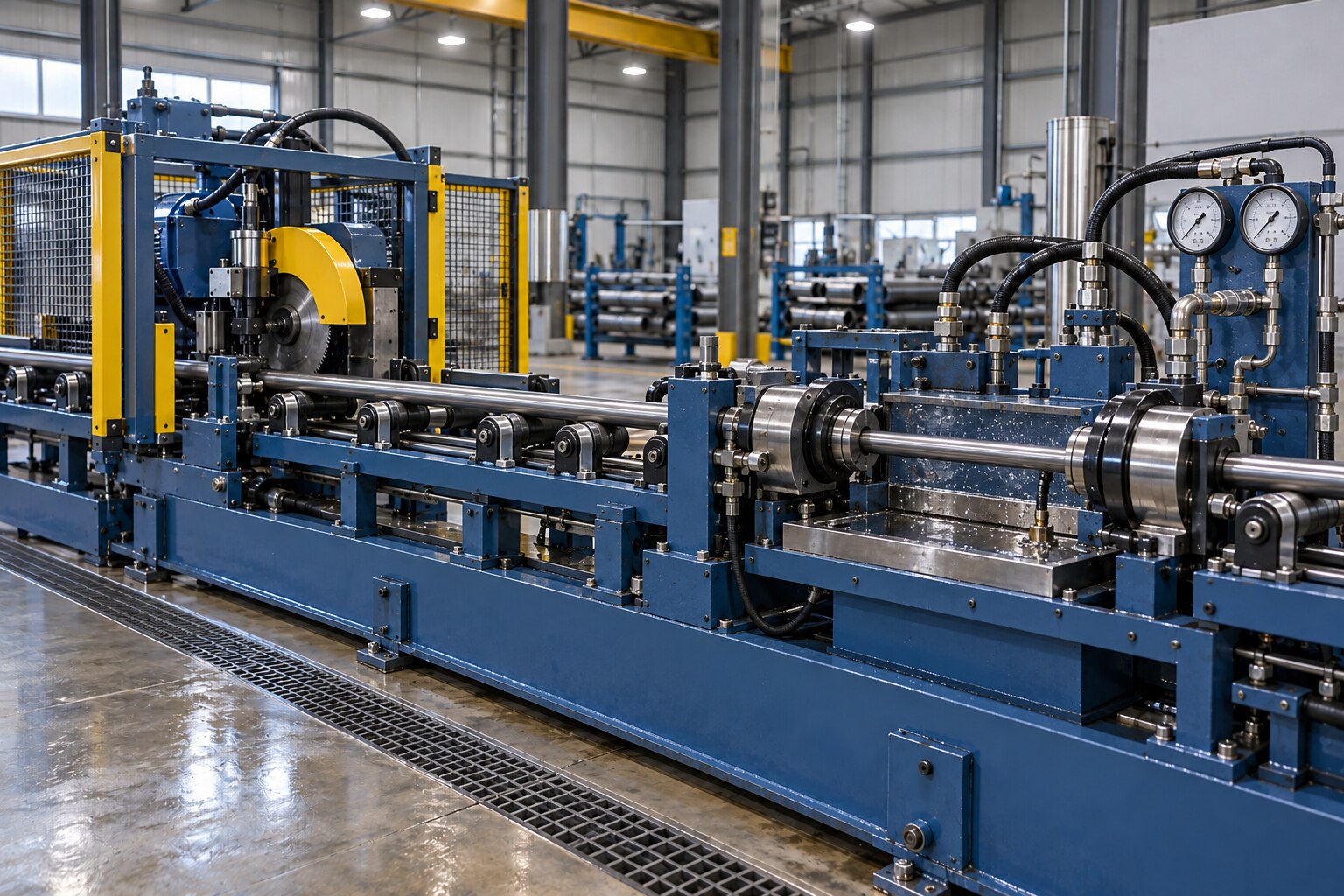
An inline pressure tester must match the tube, the production takt and the defect risks created by cutting and finishing. By defining the test location, pressure cycle, hydraulic capacity, sealing system and controls, you can specify equipment that finds tube-wall leaks without turning seal leakage or process variation into false rejects.
Key takeaways
- Define tube size, takt time and pressure standard before selecting equipment.
- Place testing after cutting only when end geometry supports reliable sealing.
- Size the pump and accumulator for simultaneous tubes and the real cycle.
- Specify leak detection, instrumentation and acceptance tests before equipment integration.
Start with the tube range, production takt and pressure standard
Before selecting a pump or test head, define the pressure testing machine requirements from the product range, production takt and governing standard. Record outside diameter, wall thickness, tube length, steel or stainless-steel grade, weld type, straightness, ovality, end condition, maximum line speed, cut-length tolerance, production rate and the number of tubes tested simultaneously.
- Name the exact standard and edition, such as API 5L for line pipe or the applicable EN 10217 series standard for pressure-purpose welded tubes. Copy its pressure formula or pressure table, hold time and acceptance criterion into the purchase specification; do not substitute a generic pressure setting.
- Rate the pressure testing machine above the maximum operating test pressure and the transient produced by fast filling or valve closure.
- Calculate cycle time as end sealing + filling + air removal + pressure ramp + stabilization + pressure hold + depressurization + unloading. Compare that result with the cutting takt.
| Cycle-time result | Production consequence | Required arrangement |
|---|---|---|
| Test cycle is at or below takt | One position can match output | Verify the rate at minimum and maximum tube volume |
| Hold time exceeds takt | Faster pumping cannot remove the bottleneck | Add parallel test positions, or use a rotary or shuttle tester |
| Testing intermittently blocks cut lengths | Finished tubes wait for testing | Add an accumulation buffer sized for the residence time |
The pressure standard determines the test duty; the line layout determines whether that duty meets production rate. Record seal and fixture volumes in the cycle calculation, especially for short tubes, because dead volume can dominate filling time.
Choose where testing belongs in the cutting and finishing sequence
Place testing after the last operation that can damage the pressure boundary. Testing a continuous tube before flying cut-off reduces sealing, filling and draining cycles, but it cannot find cut-induced leaks, end cracks, burr damage or later forming damage.
Testing each finished length verifies the shipped part and isolates scrap to one piece, at the cost of loading, sealing, draining and discharge time for every tube.
| Option | Throughput effect | Defect coverage |
|---|---|---|
| Continuous tube before cut-off | Fewer test cycles and higher potential throughput | Misses defects introduced by cutting, end work or later forming |
| Finished cut length after cut-off | Lower throughput because every piece receives a complete cycle | Verifies the shipped part and identifies the defective piece |
| Intermediate test station | Balances cycle time with final-end constraints | Tests before end facing, then requires final end-quality inspection |
Specify the line sequence explicitly:
- Tube forming and weld inspection
- Required straightening
- Pressure testing
- Flying cut-off
- End facing or deburring
- Final straightening
- Inspection and bundling
If end facing changes the finished product but the pressure testing machine for tubes needs square, clean ends, test before facing and add a final end check. Hydrostatic testing suits leak tightness because water stores little energy.
Use air-under-water or pneumatic testing only for a justified requirement; industrial pressure testing equipment then needs remote operation, engineered guarding, exclusion zones, controlled pressurization and a written hazard assessment.
Hydrostatic testing does not replace eddy-current or ultrasonic weld inspection for lack of fusion, incomplete penetration or localized inclusions.
Size the water circuit, pump and accumulator for the real cycle
Calculate hydraulic capacity from the water volume and cycle, not nominal tube diameter. Tube volume equals π/4 × internal diameter² × test length; use consistent units, then add test-head cavities, manifolds, hoses and valves. On short cut lengths, fixture and hose volume can exceed tube volume, increasing filling time and apparent expansion.
Minimize dead volume and size a recovery tank for the complete length range.
- Fill the tube and connected circuit.
- Vent until trapped air is removed.
- Ramp pressure under controlled valve movement.
- Stabilize before starting the acceptance timer.
- Hold pressure for the specified period.
- Depressurize safely.
- Drain and prepare the position for the next tube.
Required filling flow is total test volume divided by permitted filling time, plus flow for air purge and any simultaneously filling test position. State these values in the pressure testing machine requirements; pump flow alone cannot overcome a hold-time bottleneck.
Size the accumulator for make-up volume during pressure hold, including water compressibility, valve response and the permitted pressure band. Require the supplier’s hydraulic calculation; an accumulator is not simply a larger water tank. Measure pressure at, or hydraulically close to, the tube, and include losses through valves and passages.
Use filtered water, a drainable manifold, recovery, drying and corrosion control. Dry carbon-steel tubes promptly and limit standing water. For stainless steel, specify chloride limits, temperature range and filtration to prevent contamination.
Prevent false leaks at seals, cut ends and pressure instrumentation
Distinguish a tube-wall leak from fixture leakage by proving the complete sealing and measurement chain, not by treating every pressure drop as a defective tube.
1. Specify test-head stroke and seal geometry for every cut-end condition: squareness, burr height, ovality, concentricity, weld-bead profile and permitted end deformation. A seal that passes a square, deburred end can leak on a sheared or oval end. Record the maximum sealing force that will not deform the tube.
2. Define the seal material, such as EPDM or polyurethane, for the test fluid and pressure; state its replacement interval in cycles, visible wear limit and tool-free cleaning access. Validate the pressure-decay or leak-rate limit with known-good tubes, calibrated reference leaks and deliberately defective samples.
3. Allow stabilization before judging decay. Water-temperature change, trapped air, hose or fixture expansion, seal movement and pump check-valve leakage can all mimic a product leak. Measure pressure at, or hydraulically close to, the tube with a calibrated transducer, visible reference gauge, independent high-pressure cutoff and relief device.
4. Specify calibration range, traceability, zero-drift check, interval and tolerance for each instrument. Use an ISO/IEC 17025-accredited laboratory when external calibration is required.
5. In industrial pressure testing equipment, interlock pressurization with tube presence, both seals closed, guard closure, drain closed and a valid recipe. Prevent clamp release or ejection while pressure remains, and record the failed result before venting.
A pressure testing machine for tubes is incomplete without these records, interlocks and seal limits.
Turn the calculations into an integration and acceptance specification
Put these pressure testing machine requirements into the supplier request as measurable entries, not marketing ranges.
| Parameter | Required entry |
|---|---|
| Outside diameter and wall thickness | Minimum–maximum values, with seal and head changes |
| Finished length and material | Length range, grade, weld type and end preparation |
| Production | Line speed and tubes tested simultaneously |
| Test method | Product standard and edition, pressure, transient allowance, stabilization and hold time |
| Acceptance | Allowable pressure decay, water temperature, filtration, chloride or corrosion limit |
| Utilities | Recovery volume, drying method and data records |
State whether the tester receives full-length tube before flying cut-off or finished parts after cut-off. Define signal exchange with the mill, flying cut-off, end-facing station, straightener, inspection system and bundler; specify what happens when a test fails or a downstream station stops.
Ask each supplier to prove takt at the smallest and largest tube volumes, including sealing, filling, air removal, ramp, stabilization, hold, depressurization and unloading. Require seal-life assumptions, pump and accumulator calculations, guard layout, risk assessment, calibration certificates, recipe control and reject traceability.
Compare pressure test machine requirements by verified takt performance, test coverage, safe failure behavior and maintainability, not diameter range alone. Gallium Equipment Pvt. Ltd. is relevant when the specification must coordinate forming, cutting, testing, straightening and handling rather than add an isolated pressure unit.
Frequently asked questions
What information defines pressure testing machine requirements?
Record outside diameter, wall thickness, tube length, material grade, weld type, end condition, line speed, cut-length tolerance, production rate and simultaneous test count. Add the governing pressure standard and required test duration.
Where should pressure testing sit in an inline tube cutting system?
Place the test after cutting when the cut ends are stable, clean and suitable for sealing. If cutting creates burrs, distortion or chips that cause false leaks, add end conditioning before the test or test the tube before cutting.
How do you size the water circuit and pump?
Calculate the internal volume of every tube tested at once, then add test-head, piping and accumulator volume. Select pump flow for the required fill time and pressure, and check that the accumulator supplies peak demand without excessive pressure drop.
How can you prevent false leaks during tube pressure testing?
Control seal alignment, inspect cut-end squareness and burrs, support thin-wall tubes, and isolate pump pulsation from the pressure sensor. Verify leakage with a stable pressure-hold period and calibrated instrumentation.
What belongs in an acceptance specification for a pressure test machine?
State the tube range, test pressure, fill and hold times, cycle rate, simultaneous test count, allowable pressure loss, leak response, data records, safety interlocks and integration points with cutting and finishing equipment.
Keywords