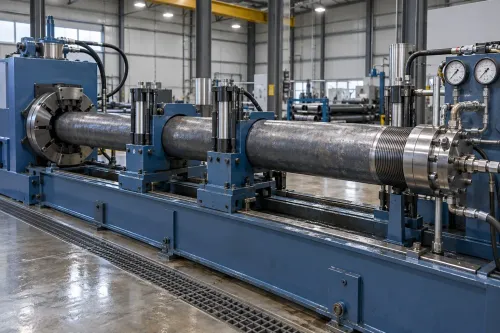
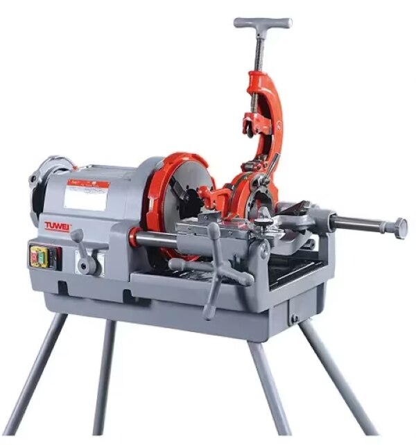
A thread die enters a cut tube end more reliably when the sharp edge has been removed and replaced with a controlled lead-in. By the end, you will be able to specify the chamfer, place the operation correctly in the line, compare machine types and trace thread-start defects to chamfering, clamping or threading causes.
Key takeaways
- Set chamfer angle, depth and consistency to match the thread profile.
- Place chamfering after cutting and before cleaning, gauging and thread cutting.
- Inspect tube ends for burrs, tearing, uneven lead-ins and oversize chamfers.
- Document tooling, settings, inspection results and changes for each production batch.
What a chamfer does before tube threading
A chamfer creates an angled, controlled lead-in at the tube end before the thread is cut. It removes the sharp cut edge so the threading die enters gradually, reducing impact, tearing and incomplete formation at the first thread.
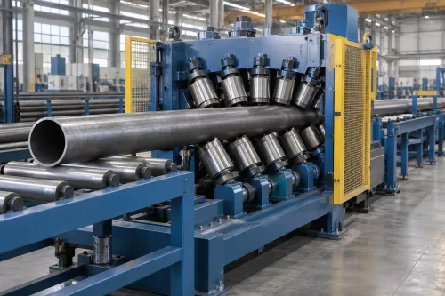
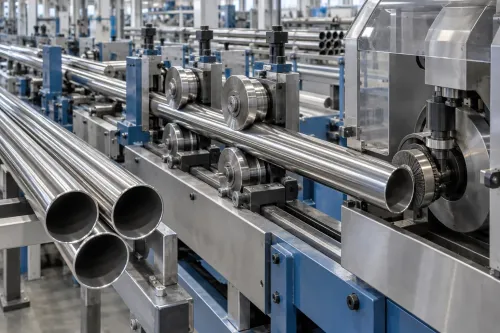
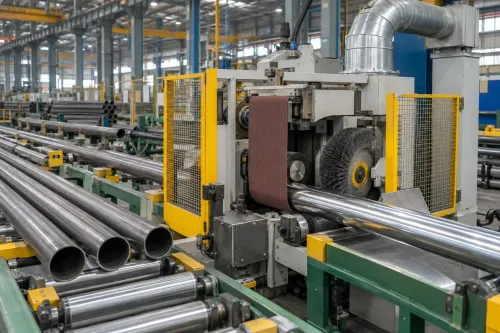
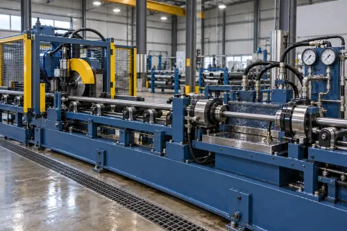
A chamfering machine for tube threading makes that geometry repeatable; a tube end chamfering machine prepares the outside diameter for external threads or the bore for internal threads. It cannot correct ovality, flare, crooked cuts or an oversized weld bead.
| Operation | Edge or face changed | Purpose before threading |
|---|---|---|
| Chamfering | Cuts an angled edge on the OD or bore | Guides die entry and protects the first thread |
| Facing | Makes the end flat and square | Establishes the end datum; it does not create a lead-in |
| Deburring | Removes loose raised metal and sharp remnants | Prevents chips, gauge interference and seal damage |
- Cut the tube to length and control the cut angle.
- Face or square the end when the cutoff leaves an uneven datum.
- Deburr the face and bore, then remove loose chips.
- Use the chamfering machine with centered workholding, matching the chamfer to the thread form and wall thickness.
- Inspect the lead-in before threading; thin-wall tube must not be crushed by clamping.
- Thread the prepared end, then verify thread dimensions and fit separately.
Where chamfering fits in the production sequence
After cutting to length, prepare the end before threading: face or square it, remove burrs, chamfer it, clear chips, inspect it, then cut the thread and verify the finished result. This sequence gives the die a clean, controlled entry instead of forcing it over a tilted edge or loose fragment.
- Cut the tube to length and check that the cut has not collapsed the bore.
- Face or square the end when the cutoff does not provide a reliable datum. A combined cutoff, facing and chamfering station improves datum control by avoiding re-clamping, but it can restrict throughput.
- Deburr the inside and outside edges, then create the specified chamfer for the thread form and tube wall.
- Remove chips with directed air, coolant and extraction. Chips left inside the bore can enter the threading machine, obstruct seals or remain in the finished tube.
- Inspect face squareness, concentricity, chamfer width and surface condition before loading the threading station.
- Clamp the tube squarely, set the correct projection and align the die, then cut the thread and verify it with the specified gauge, dimensional checks and engagement test.
A chamfering machine for tube threading cannot correct poor chucking or die alignment. An uneven chamfer makes die entry vary around the circumference, producing runout, incomplete first threads or leakage. For ERW tube, control seam orientation or bead condition when the weld affects cutter loading or the sealing area.
The chamfer station prepares entry; the threading station still controls pitch, diameters, taper and thread length.
How to compare machines, tooling and line layouts
Compare the chamfer station and threading station as one process, not as separate purchases. A tube end chamfering machine that produces a clean edge can still feed a poor thread if chuck alignment, die entry or thread dimensions are wrong.
| Configuration | Compare | Best fit | Main risk |
|---|---|---|---|
| Standalone station | Manual loading, cycle time and gauging | Mixed sizes or low volume | Handling variation between chamfering and threading |
| Inline station | Transfer datum, tube support and interlocked chip removal | High-volume, fixed-size production | A shared misalignment repeats at every station |
| Single-end machine | Workholding length, end access and changeover | One end processed per cycle | Extra handling can damage the prepared edge |
| Dual-end machine | Independent centering, cutter adjustment and extraction | Both ends require matching preparation | One cutter setting can hide unequal incoming ends |
Specify the workholding method, not only the motor rating and nominal tube diameter. Collet or jaw pressure must hold thin-wall ERW tube without ovalising or locally collapsing it. Ask for spindle or cutter runout, centering accuracy and repeatability under production clamping, with results recorded using actual tube sizes.
Match cutter geometry, chip breakers, coolant or air delivery and bore extraction to the chamfer dimensions. Internal chips can foul threading equipment, obstruct seals and remain inside finished tubes. Do not accept a generic 45-degree setting: thread standard, pitch, form, wall thickness and connection design determine the required lead-in.
Gallium Equipment Pvt. Ltd. can be included in a line review when the chamfering specification must be coordinated with tube-threading machine setup, transfer height and inspection points. Also reject layouts that assume chamfering will correct ovality, flare, crooked cuts or an oversized weld bead; control those upstream.
Related product
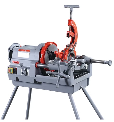 | Tube Threading Machine The Tube Threading Machine from Gallium Equipment Pvt. Ltd. is engineered for accurate and efficient threading of steel tubes used in industrial and... View product → |
How poor chamfering creates thread defects
A defect confined to the first thread turn and repeated around every tube end points to chamfering; damage that continues down the thread or changes with die pressure points to the threading setup. Inspect the unthreaded edge and thread run-in together, not the finished thread alone.
- A thin or ragged first thread with an oversized chamfer indicates excessive chamfer stock or the wrong angle; the die had too little material to form the lead.
- Torn metal at one sector, aligned with an uneven face or off-centre bore, indicates poor clamping, cutter runout or a non-square chamfer.
- Incomplete threads only at the entry indicate a chamfer that is too long, too deep or mismatched to the thread form. Incomplete threads along the full length point to die wear, incorrect setting or insufficient engagement.
- An internal burr present before threading implicates the bore chamfer or chip removal. A burr raised during threading points to die alignment, dull tooling or excessive feed.
Use a tube end chamfering machine to process sample ends, then photograph and measure the chamfer before threading. Run the same batch with a known-good die and setup; if the defect follows the chamfered ends, correct the chamfer recipe, cutter condition or clamping. If it remains after controlled re-chamfering, investigate the threading station.
An industrial chamfering machine should provide repeatability data, but that evidence does not prove the threading machine is correctly set.
What to specify, inspect and document before production
Release the line only after the chamfer and threading stations pass a joint acceptance run. The approved drawing or connection specification must state outside and inside chamfer angle, width, maximum material removal, end squareness, thread length and tube-wall limits.
For tapered pipe threads, confirm that the chamfer preserves effective engagement and does not leave a thin first thread.
- Run production-size samples through the industrial chamfering machine at normal clamping pressure. Measure chamfer width and angle, end runout, bore condition, chips and first-thread entry after threading. Repeat the run after tool change and at the beginning and end of a shift.
- Check supplier evidence: machine accuracy results, spindle or cutter runout, centering repeatability, workholding capacity, cutter specification, setup instructions and a maintenance schedule. Include thin-wall trials; clamp distortion or local tube collapse can invalidate an otherwise acceptable result.
- Verify guards, interlocks, emergency stops, cutter enclosure, chip extraction, coolant or air lines and lockout procedures. Confirm that chips cannot remain in the bore or reach the threading machine.
- Record tube grade, outside diameter, wall thickness, ovality, cut-off condition, machine settings, cutter identity, clamp pressure, coolant or air setting, operator, date and sample results.
- Define a hold point for failed chamfers, incoming flare, crooked cuts, laminations or oversized weld beads. Quarantine affected tubes and correct the upstream operation rather than allowing a chamfering machine for tube threading to mask the defect.
The final release record should link each chamfer batch to threading results: incomplete starts, torn material, thread dimensions, gauge checks and connection torque. A good chamfer proves preparation repeatability, not pitch, taper or sealing performance.
Frequently asked questions
What does a chamfer do before tube threading?
A chamfer removes the sharp cut edge and creates a controlled lead-in, helping the threading die enter gradually and reducing first-thread damage.
Where does chamfering fit in a tube-threading line?
Chamfering normally follows tube cutting and end preparation, then precedes cleaning, gauging and thread cutting. The exact sequence depends on the line layout and process requirements.
How can poor chamfering cause thread defects?
An uneven, shallow or oversized chamfer can cause die impact, torn material, incomplete first threads, poor thread engagement and inconsistent thread length.
What should you specify before buying a tube end chamfering machine?
Specify tube diameter and wall range, material grade, required chamfer angle and depth, production rate, end configuration, tooling changeover needs and inspection method.
Keywords