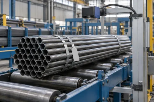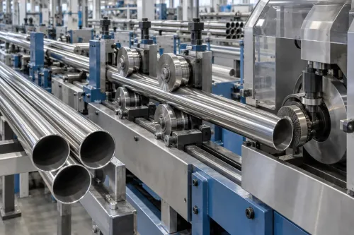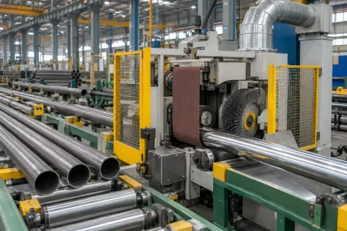
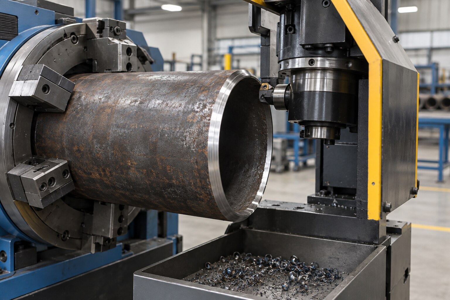
A cut pipe end is not automatically ready for welding, threading, coupling or flange assembly: burrs, poor squareness, an inconsistent root face and excess heat can all cause downstream failures. By the end, you will know which machine arrangement and end geometry to specify, how to compare alternatives, and how to verify the finished pipe before it enters production.
Key takeaways
- Match the machine to pipe diameter, wall thickness, material and required end profile.
- Use facing and beveling tools that leave the specified angle, land and surface finish.
- Control chuck alignment, cutting speed, feed and tooling wear during every production run.
- Specify measurable acceptance checks for dimensions, burrs, threads, runout and repeatability.
What pipe end preparation must achieve
Pipe End Preparation is a controlled set of operations, not a single cut. It prepares geometry, length and surface condition for welding or reliable assembly.
- Outside-diameter beveling creates the weld angle and root face, or land.
- Inside-diameter deburring removes the internal lip and preserves a smooth bore transition.
- End facing establishes a square end plane and finished length.
- Chamfering breaks a sharp edge without replacing the specified weld bevel.
- Burr removal cleans the cutoff profile, removing loose metal, gouges and tears.
A 37.5-degree bevel per side, producing a 75-degree included angle, is common for butt welding but is not universal. ASME B16.25 addresses butt-welding-end dimensions, while the applicable pipe standard and qualified welding procedure determine the actual bevel angle, land width, counterbore or compound preparation.
Check more than the angle. The finished end needs controlled end squareness, concentricity between the bevel and pipe axis, uniform root-face width, acceptable runout, a defined bore transition and a clean bevel surface with controlled roughness. Scale, oxide, coolant residue and embedded abrasive can contaminate the weld.
A visually sharp edge is not necessarily weld-ready. Excessive land can restrict root penetration; an undersized or uneven land increases burn-through risk and complicates root control. These measurable requirements distinguish effective Pipe Finishing from simply cutting the pipe.
Which machine performs the cut, face, bevel or thread
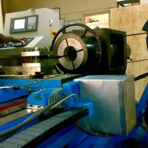
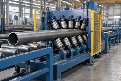
A Beveling Machine performs the weld-preparation cut: its beveling head cuts the outside-diameter weld angle and root face. The same head can be combined with internal beveling or deburring to preserve the bore transition.
| Option | Operation | Best fit and limitation |
|---|---|---|
| Beveling Machine | Cuts the external bevel; may also bevel inside or deburr | Butt welding; specify angle and land. It can prepare socket-weld ends when the drawing requires a chamfer or controlled entry. |
| End Facing Machine | Removes material to establish a square end plane and finished length | Flanged assemblies, grooved couplings and clean seating surfaces. It does not create a weld bevel unless fitted with a dedicated beveling tool or combined head. |
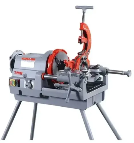
| Pipe threading machine | Cuts external or internal threads | Threaded connections; it does not produce a butt-weld bevel or a controlled flange-facing surface. |
| Lathe | Turns, faces, bores and bevels with flexible tooling | One-off or varied work, but chucking, measurement and handling can cost more time. |
| Manual grinder | Removes metal by operator-guided abrasive action | Repairs and low-volume work; bevel angle, land and squareness depend heavily on operator consistency. |
| Cold saw | Cuts pipe to length | Fast cutoff before finishing, but tooth marks and a cutoff burr can remain. |
| Abrasive or thermal cutter | Abrasive wheel cuts with possible abrasive contamination or heat-affected material; thermal cutting leaves oxide, dross or a heat-affected edge | Use a facing or beveling pass when the seating or weld surface must be clean. |
Select the finishing machine for the upstream cutoff condition, not nominal diameter alone. A controlled bevel supports root penetration; a faced end supports gasket, coupling or flange seating, while threading requires a thread-making machine rather than either operation.
How to choose the machine configuration and capacity
Choose capacity from the complete part specification, not the outside-diameter range alone. Record outside diameter, wall thickness, material grade, pipe length, bevel angle, root-face width and tolerance, allowable runout, end squareness, and complete cycle time from loading through transfer.
| Configuration | Best fit | Main trade-off |
|---|---|---|
| Single-end | Mixed lengths, short batches | Lower alignment complexity; handling can limit output |
| Double-end | High-volume identical lengths | Both ends finish in one loading cycle, but synchronization, alignment and chip clearance become critical |
| Stationary pipe with orbital head | Long or heavy pipe | Avoids rotating the workpiece; head travel and access govern capacity |
| Rotating pipe with cutting head | Compact, repeatable parts | Simpler cutter path; clamping and balance govern accuracy |
Specify external beveling, internal beveling or both. External cutting forms the weld angle; internal cutting removes the bore lip and controls the transition. Automatic stops and transfer systems improve output only when they locate the pipe repeatably without striking the finished end.
A diameter range does not prove capacity. Cutting torque and power also rise with wall thickness, high-strength or stainless grades, bevel geometry, tool diameter, cutting speed and chip load. Compare those values against the required cycle, not maximum spindle speed. A Beveling Machine belongs in tube finishing equipment when weld preparation is the bottleneck.
Thin-wall ERW tube needs split collets, internal mandrels, close-fitting supports or controlled clamping pressure to prevent crushing and ovalization. Specify seam orientation or tracking when the weld seam must reach a clock position. Reject a design that cannot hold runout and squareness after clamping, cutting and unclamping.
How to run the operation and control tooling effects
Measure the pipe outside diameter, wall thickness and length, then confirm the material grade before loading. A practical sequence is:
- Load the pipe against a repeatable stop.
- Clamp firmly without collapsing or ovalising the wall.
- Align the pipe axis with the cutting head.
- Set cutter position, bevel angle and root-face (land) width.
- Face the end to establish length and squareness.
- Cut the outside bevel.
- Remove the internal lip and cutoff burr.
- Clear chips without dragging them across the finished surface.
- Inspect the end and record dimensions, tool condition and result.
Select replaceable carbide inserts or cutters for the material: carbon steel, stainless steel, alloy steel and galvanized pipe do not share one universal insert or cutting condition. Stainless surfaces need clean, dedicated handling to prevent iron contamination.
Choose speed, feed and depth for the actual alloy, wall thickness and production rate; excess heat can damage the edge or alter its condition.
Tool wear progressively changes bevel angle, land width and surface finish. Use accessible tool-position adjustment, tool-life checks and first-piece inspection, followed by periodic checks during the run. This control is central to consistent Pipe Finishing and tube finishing equipment.
| Option | What it means | Main trade-off |
|---|---|---|
| Dry machining | No fluid | Simpler chips and housekeeping, higher tool heat |
| Flood coolant | Continuous fluid flow | Better cooling and tool life, plus filtration, wet chips, corrosion and wastewater duties |
| Minimum-quantity lubrication | Fine lubricant mist | Lower fluid use, but requires mist control and precise delivery |
Inspect the end after each setup change, not only after a visible failure.
What to put in the purchase specification and acceptance check
Write the purchase specification as an acceptance sheet, not a catalogue comparison. State the complete Pipe End Preparation requirement and make every output measurable on sample parts.
1. Define the operating envelope: outside diameter, wall-thickness range, material grades, pipe length, single- or double-end processing, external and internal operations, and seam-orientation or clock-position requirements. Specify bevel angle and tolerance, root-face or land width and tolerance, bore transition, end squareness, allowable runout, burr height, bevel-surface roughness, concentricity and finished-length tolerance.
2. Name the governing API, ASTM, EN or customer standard and the welding procedure. API Specification 5L covers seamless and welded line pipe, so “standard bevel” cannot replace the required product end condition; ASME B16.25 also does not set your machine’s production rate. Record the required geometry, including any counterbore or compound preparation.
3. Compare suppliers using the complete cycle: loading, locating, clamping, facing, beveling, chip evacuation, gauging, unclamping and transfer. Measure parts for angle, land uniformity, squareness, runout, burrs, roughness, concentricity and gouges. Do not rank machines by spindle speed alone; an automatic stop that damages the finished end reduces usable output.
Ask Gallium Equipment Pvt. Ltd. to translate your pipe schedule, welding procedure and production rate into a complete Pipe Finishing specification. Make sample-part inspection and documented first-piece results conditions of acceptance, including repeatability after the machine reaches normal operating temperature.
Related product
 | We have full range of pipe threading machine, manual pipe threading machine, electric pipe threading machine, conduit electrical pipe threading... View product → |
Frequently asked questions
What must pipe end preparation achieve?
It must produce the specified pipe length, end geometry, bevel angle, root face, surface condition and alignment for welding or assembly.
Which machine performs cutting, facing, beveling or threading?
A cut-off machine separates the pipe, an End Facing Machine squares the end, a Beveling Machine creates the weld bevel, and a dedicated threading machine forms threads. Combination machines perform several operations in one setup.
How do you choose a pipe beveling machine configuration?
Compare the working diameter range, wall thickness, pipe material, production rate, number of spindles, clamping method, required end profiles and available automation.
What should you check when accepting a pipe finishing machine?
Run sample pipes through the machine and measure cut length, face squareness, bevel angle, root-face width, burrs, thread dimensions, runout and cycle time against the purchase specification.
Keywords