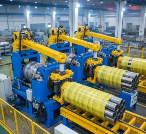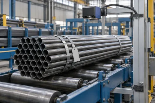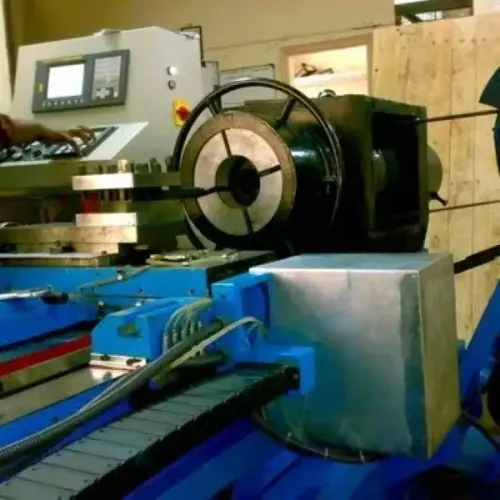
A cut tube can leave the saw with an angled face, burr, collapsed edge or the wrong finished length. By the end, you will know what end facing removes, when the operation belongs in an ERW line, and how to compare machine types, capacity, quality checks and safety features before specifying equipment.
Key takeaways
- Measure tube diameter, wall thickness, length, material, and cut condition first.
- Use facing tools to control end squareness, length, burrs, and surface tearing.
- Verify runout, end-length tolerance, squareness, burr height, and repeatability.
- Specify guarding, chip removal, extraction, access, and safe tube handling before purchase.
What does an End Facing Machine do to a tube end?
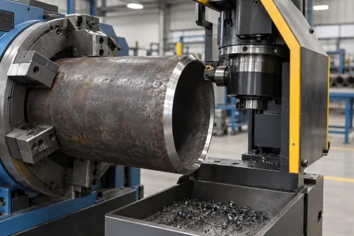
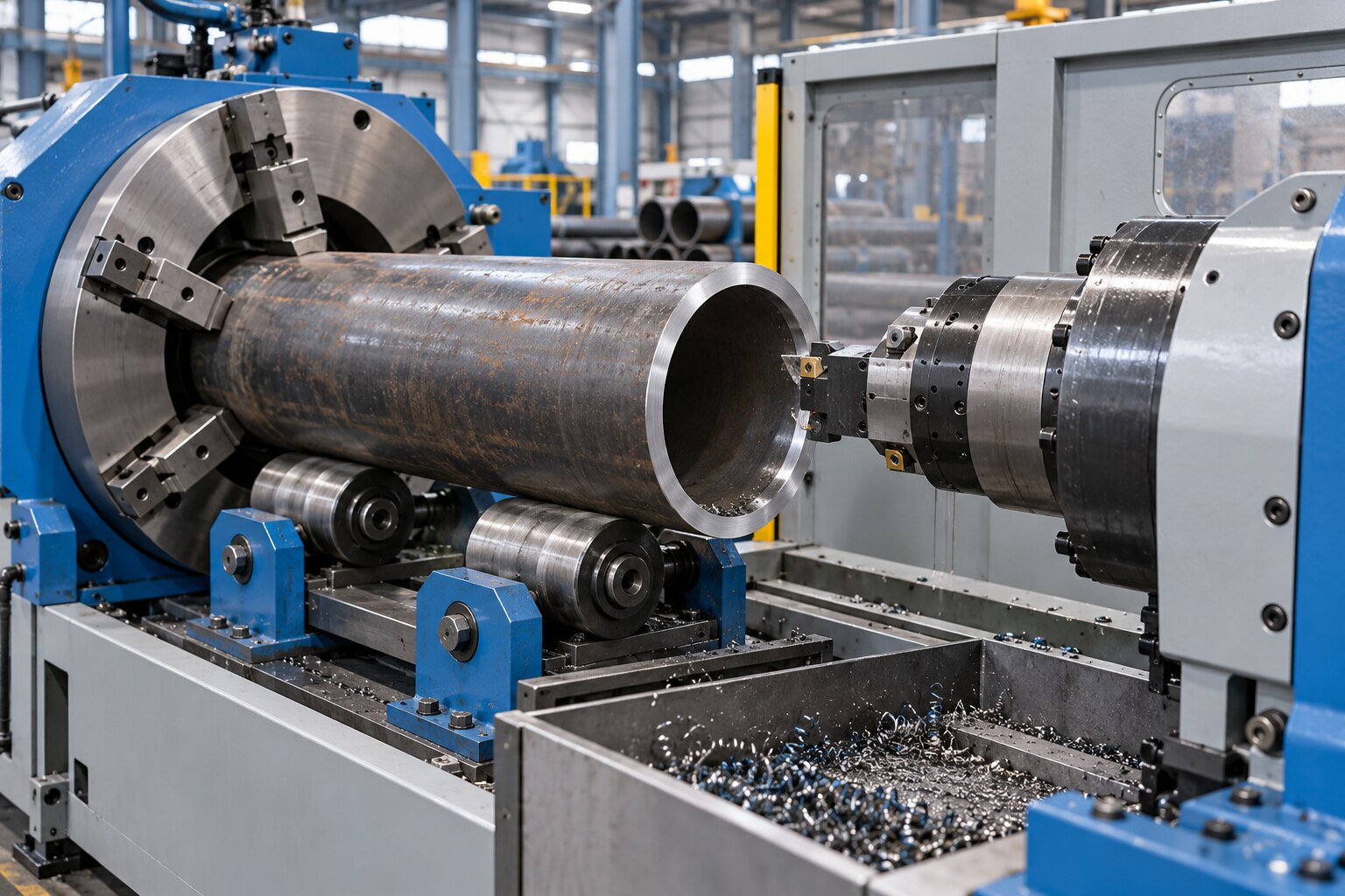
An End Facing Machine machines a cut tube end square to the tube axis while removing saw or shear burrs. The operation establishes end length and end squareness, correcting angled cuts, uneven end lands, burrs, collapsed edges, inconsistent end length and surface tearing.
It is not the same as these operations:
- Sizing corrects the tube’s outside diameter, inside diameter or cross-sectional shape in the tube mill’s sizing stands. Facing does not replace those stands.
- End forming changes the tube profile, such as reducing, expanding, flaring or shaping the end.
- Chamfering creates a specified angled transition at the inside edge, outside edge or both.
- Beveling creates a larger angled weld-preparation geometry, often with a defined bevel angle and land.
- Deburring removes sharp raised material but does not necessarily establish a precise end length or square face.
- Threading cuts a helical thread into the tube end.
- A cut-off saw separates the tube to length; it does not finish the cut face to the same controlled condition.
The facing allowance changes the finished tube length. State in the cut-to-length calculation whether the length tolerance applies before facing or after facing; otherwise a tube that measures correctly at the saw can become short after machining.
Specify measurable perpendicularity or end-squareness limits, not merely a “clean end.” A facing operation is useful when the downstream coupling, socket, gauge or welding fixture depends on a consistent, square end.
How does an end-facing cycle work in production?
A production cycle combines material handling with machining; spindle speed alone does not determine output. Practical cycle time includes loading, end location, clamping, tool movement, cutting, chip removal and transfer.
- Load the cut tube onto the entry supports and locate its end against a stop, probe or length-measuring system.
- Clamp it with the selected support arrangement, then verify that the tube cannot rotate.
- Approach the cutter at controlled feed and speed, keeping the tool aligned with the tube axis.
- Face or mill the end until the specified length, squareness and burr condition are reached.
- Evacuate chips with gravity, air blast, vacuum or coolant so chips do not mark the end or obstruct clamping.
- Withdraw the tool clear of the workpiece before releasing pressure.
- Unclamp, move the tube to inspection, check length and perpendicularity, then unload it to the next process or bundle.
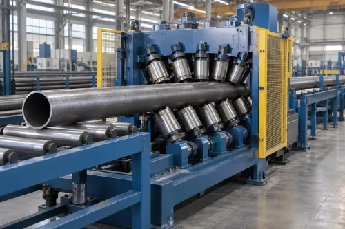
Two-end machines face both ends simultaneously, reducing transfer time. They require matched end locations, more complex tooling and a layout that supports both ends; sequential processing simplifies access and changeovers.
Face after ERW production or sawing when burrs, angled cuts or uneven lands remain. Repeat it after straightening, heat treatment, threading or a later cut-to-length operation when those processes disturb squareness or length.
For thin-wall tube finishing equipment, use segmented jaws, collets or expanding mandrels with adequate support length and controlled force. Hard external jaws can dent or ovalize the tube; weak clamping causes rotation and chatter. Fix ERW seam orientation when a stop, asymmetric tool or fixed clamp places the seam in a sensitive position.
Which machine type and operating envelope fit the tube?
Choose by the smallest wall thickness and the required end geometry, not by maximum outside diameter alone.
| Option | What it does | When it fits |
|---|---|---|
| Dedicated facing machine | Mainly faces ends square and removes burrs | High-volume face-only work |
| Sizing & End Finishing Machine | May combine cross-section sizing with facing, deburring, chamfering or beveling | Downstream ERW lines needing both operations |
| Chamfering Machine Beveling Machine | Cuts a controlled inside or outside angled edge; beveling may add a weld-preparation land | Coupling, welding or assembly preparation |
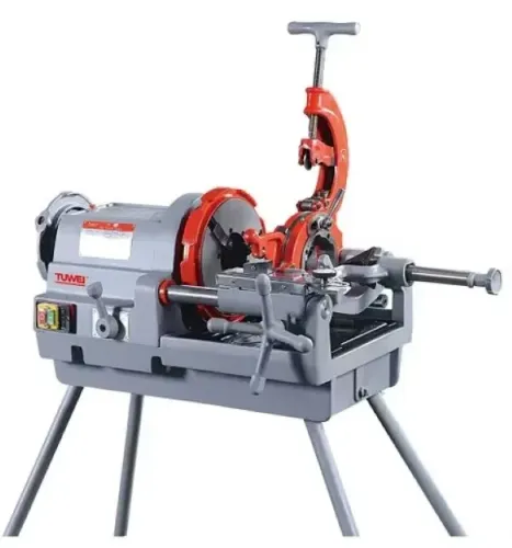
| Manual lathe or secondary machining cell | Flexible, operator-loaded machining with slower handling | Low volume, frequent changes or unusual geometries |
A combined name does not prove that every operation occurs in one station. Require the supplier to list each operation, tool and station separately.
Your tube finishing equipment specification should state:
- Material grade and tensile strength; outside-diameter, wall-thickness and tube-length ranges
- Smallest wall thickness, incoming ovality and bow limits
- One-end or two-end processing per cycle
- Dry cutting or coolant cutting
- Finished length and end-squareness tolerances
- For chamfering or beveling: inside or outside edge, angle, land width, root-face requirement and residual-burr limit
Request cycle time for a representative OD, wall, grade, cut length and end geometry. Include loading, end location, clamping, tool approach, cutting, chip evacuation, withdrawal, unclamping and transfer—not spindle speed alone.
Gallium Equipment Pvt. Ltd. belongs in the comparison only after it documents this application-specific envelope and demonstrates the required operation on representative tubes.
How do you verify the finished tube and the supplier’s claims?
Verify an End Facing Machine by measuring the finished tube, not by accepting its spindle speed or programmed settings. Set dimensional and visual limits before the trial, then record actual results after facing.
Check each sample for:
- Finished length and end squareness, or perpendicularity to the tube axis
- OD, ID and ovality at the faced end
- Burr height, surface tearing and clamp dents
- Chamfer or bevel angle, land width and residual edge damage
- Fit in the intended coupling, socket, gauge or welding fixture
For butt-welding service, put the bevel angle, root face or land and edge condition in the welding specification. ASME B16.25 is a reference for butt-welding-end preparation, but it does not define every tube product’s dimensional or mechanical acceptance requirements.
Require a run-off using production-speed ERW material rather than individually selected samples. Include the actual burr variation and both the largest and smallest specified wall conditions. Record first-piece setup time, sustained cycle time, tool life, reject rate and finished-length results after facing.
Ask whether carbide indexable tools, the coolant choice and insert geometry control burrs without distorting thin wall. The trial should expose failure: excessive radial engagement or the wrong edge geometry can worsen burr formation.
Accept the machine only when its measured tube results remain within your criteria during sustained production, not just during a clean first pass.
What layout and safeguards make end finishing usable every day?
An inline End Facing Machine must sit between the cut-off, transfer table, inspection point and bundle or packing process without breaking length control. Add the facing allowance to the cut-to-length calculation, and state whether the length tolerance applies before or after facing; otherwise correct saw lengths become rejected short tubes.
The station must absorb variation in cut position, tube bow, ovality and burr size at production speed. A manual lathe handles individually selected tubes; an inline station needs guided transfer, reliable end location, compliant clamping and tooling that will not amplify incoming variation.
Specify these safeguards before comparing cycle times:
- Guard the point of operation and every rotating part.
- Interlock access doors so cutting cannot continue while they are open.
- Contain sharp chips and protect operators during loading and unloading.
- Provide safe, unobstructed tool-change access.
- Control coolant mist and airborne metal particulate with extraction or filtration.
| Manual lathe or secondary cell | Automatic transfer and two-end processing |
|---|---|
| Higher operator handling, floor space and work-in-process | Lower handling, with coordinated transfer and inspection |
| Flexible for irregular pieces and occasional changes | Better sustained throughput when both ends follow the same cycle |
| Separate inspection and loading decisions | Inspection can be built into the flow |
Choose tube finishing equipment by total operating cost, not spindle speed. Balance throughput, changeover time, operator exposure, tooling access and maintenance against rejects caused by short tubes, poor end preparation or missed inspection. Include tool life and chip removal in the run-off, using production material rather than hand-selected samples.
Frequently asked questions
What does an End Facing Machine do to a tube end?
It machines the cut end square to the tube axis, removes saw or shear burrs, controls end length, and corrects angled cuts, uneven end lands, collapsed edges, inconsistent length, and surface tearing.
How does an end-facing cycle work in production?
The machine locates and clamps the tube, advances a facing tool across the end, retracts after reaching the programmed position, and releases the finished tube for inspection or the next operation.
Which machine type and operating envelope fit the tube?
Select the machine from tube outside diameter, wall thickness, length, material, cut condition, required tolerance, throughput, and whether you need facing, chamfering, sizing, or multiple operations.
How do you verify the finished tube and the supplier’s claims?
Run representative tubes and record end length, squareness, runout, burr height, surface condition, cycle time, tool life, and repeatability against your drawings and acceptance limits.
What layout and safeguards make end finishing usable every day?
Provide safe loading and unloading space, guarded cutting zones, chip control, extraction where needed, interlocked access, emergency stops, stable tube support, and clear maintenance access.
Keywords